English
 Español
The global shift toward renewable energy sources has fundamentally elevated the importance of high-capacity and reliable Energy Storage Systems (ESS). At the core of ESS performance, longevity, and safety lies a critical, yet often overlooked component: the Energy Storage Heat Sinks Housing. This enclosure is far more than a simple protective shell; it is an active participant in the thermal regulation process. In a world demanding greater energy density and faster charge/discharge cycles, effective thermal management determines the economic viability and operational life of the entire battery system. This article delves into the sophisticated design, material science, and strategic integration that define modern, high-performance ESS cooling solutions, ensuring optimal operation and maximizing investment returns.
Content
- 1 The Critical Role of thermal management solutions for battery energy storage
- 2 Design and Material: die-casting aluminum enclosures for ESS cooling
- 3 Advanced Cooling Integration: optimizing liquid cooling plates for energy storage systems
- 4 Strategic Selection: Choosing cost-effective energy storage housing with integrated cooling
- 5
- 6 FAQ
- 6.1 What is the primary difference between a standard enclosure and an Energy Storage Heat Sinks Housing?
- 6.2 How does choosing die-casting aluminum enclosures for ESS cooling impact overall system weight?
- 6.3 Are there inherent safety advantages to optimizing liquid cooling plates for energy storage systems?
The Critical Role of thermal management solutions for battery energy storage
The fundamental requirement for any ESS is to maintain the battery cells within their optimal temperature window, typically between $20^\circ\text{C}$ and $35^\circ\text{C}$. Exceeding this range—particularly due to rapid cycling—accelerates cell degradation, leading to capacity fade, increased internal resistance, and, in severe cases, the risk of thermal runaway. Therefore, sophisticated thermal management solutions for battery energy storage are not optional features; they are foundational necessities that directly influence the system's safety certification and long-term return on investment. The design of the enclosure, including the heat sink's material and structure, becomes the primary thermal conduit, efficiently moving waste heat away from the sensitive cells. This requires a deep understanding of thermodynamics, airflow dynamics, and material science to balance cooling efficiency with weight, footprint, and manufacturing cost.
- Enhanced System Safety: Maintaining consistent cell temperatures drastically reduces the probability of hazardous thermal events, which is paramount for commercial and industrial ESS deployment.
- Extended Cycle Life: By mitigating thermal stress, an effective solution can extend the battery system's useful cycle life by 15-20% or more, significantly improving the Total Cost of Ownership (TCO).
- Maximized Performance: Batteries operate most efficiently when temperature is stable. Proper thermal management ensures the system can deliver its rated power output consistently, regardless of ambient conditions.
Understanding the Thermal Challenges in Modern ESS
Modern ESS units, especially those using high-nickel chemistry, generate substantial heat under load due to internal resistance ($I^2R$ losses). Managing this heat is challenging because the thermal conductivity between individual cells and the collective module is often poor, leading to temperature gradients—hot spots—that drastically accelerate degradation in specific areas. The Energy Storage Heat Sinks Housing must be engineered to minimize these gradients across the entire battery pack, acting as a highly conductive bridge to the ambient environment or to an active cooling circuit. The primary design challenge is to create a structure that is structurally robust (to handle vibration and shock), thermally efficient (high thermal conductivity and large surface area), and cost-efficient to manufacture at scale.
- Thermal Runaway Prevention: Designing the heat sink structure to isolate cells thermally helps contain a failure event, preventing cascade failure throughout the module.
- Gradient Mitigation: High-conductivity materials like copper or high-grade aluminum are often integrated into the primary heat transfer path to equalize temperatures rapidly.
Comparing Active vs. Passive Cooling Strategies
The choice between active and passive thermal management solutions for battery energy storage hinges on the application's energy density, power requirements, and operational environment. Passive systems, relying entirely on the heat sink housing, conduction, convection, and radiation, are simpler, more reliable (fewer moving parts), and often chosen for lower-power, distributed applications. Active systems, incorporating fans, chillers, or liquid cooling loops, are necessary for high-power, high-density applications where passive dissipation is insufficient. The most effective solutions often utilize a hybrid approach, using the heat sink housing as the primary passive cooling component, which is then supplemented by an active fluid loop.
| Feature | Passive Cooling (Conduction/Radiation) | Active Cooling (Forced Air/Liquid) |
| Complexity | Low (Relies on housing design) | High (Requires pumps, fans, sensors) |
| Cooling Power | Lower to Moderate (Limited by $\Delta T$) | High (Can maintain lower operational temperatures) |
| Energy Consumption | Zero (Except parasitic losses) | Moderate (Power required for fans/pumps) |
| Typical Application | Residential ESS, Low-Density Modules | Utility-Scale Storage, High-Density Packs |
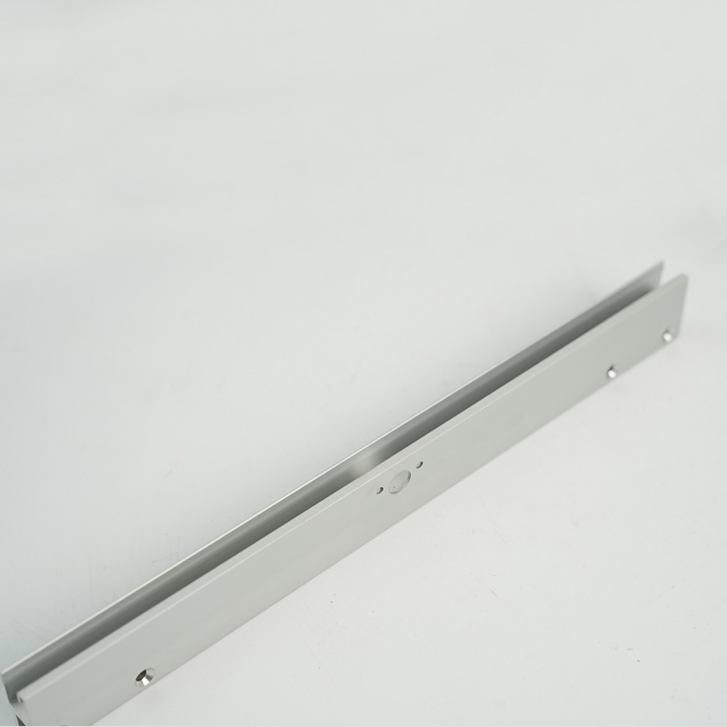
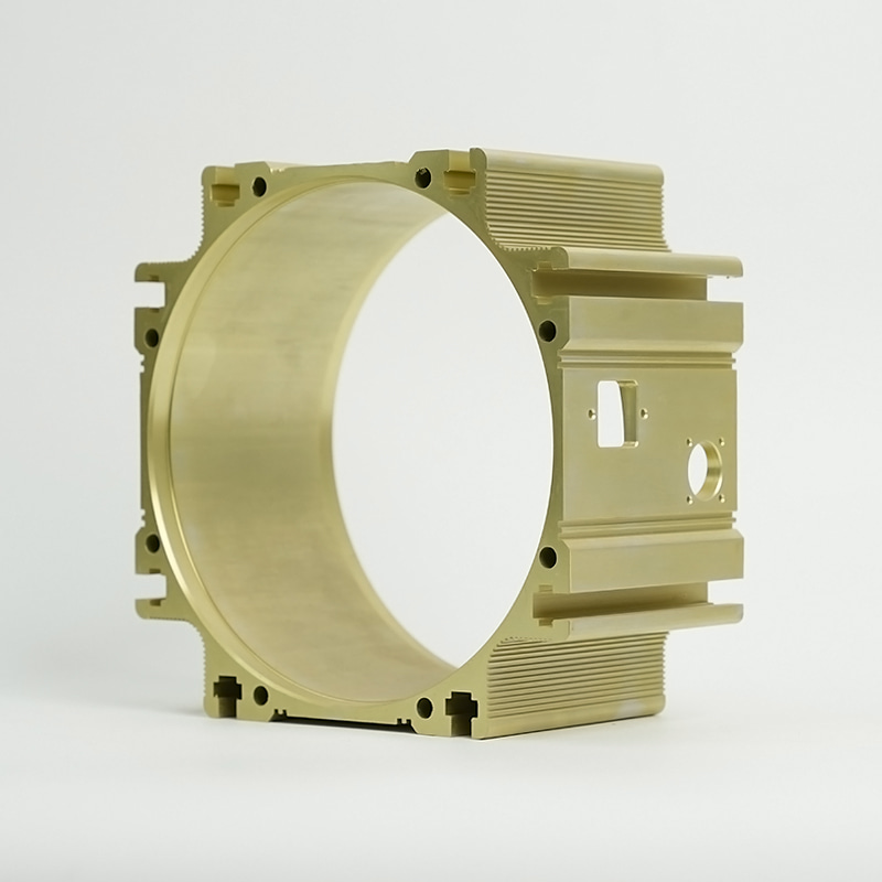
Design and Material: die-casting aluminum enclosures for ESS cooling
The manufacturing process and material selection for the external enclosure are paramount to the success of the entire thermal management system. Modern ESS increasingly relies on die-casting aluminum enclosures for ESS cooling due to the unique combination of structural integrity, low weight, and high thermal conductivity offered by aluminum alloys. Die-casting is the preferred manufacturing method because it allows for the creation of complex geometries—such as integrated fins, internal flow channels, and mounting features—in a single, high-precision operation. This monolithic approach eliminates the thermal resistance associated with bolted or welded assemblies, ensuring a seamless heat transfer path from the battery interface to the external environment or the internal cooling plate. The resulting structure is robust enough to meet stringent safety and environmental standards while being optimized for rapid, high-volume production, which is crucial for controlling the cost of the final ESS unit.
- Design Flexibility: Die-casting allows engineers to integrate complex fin patterns and internal channels directly into the structural housing, maximizing the surface area for heat exchange.
- High Repeatability: The process delivers extremely tight tolerances, ensuring that every housing unit provides consistent thermal and mechanical performance across mass production batches.
- Weight Reduction: Aluminum provides the best balance of strength-to-weight ratio among high-conductivity metals, minimizing the overall mass of the ESS container.
Why Aluminum Dominates Energy Storage Heat Sinks Housing Fabrication
Aluminum alloys, particularly those with high silicon content (e.g., A380, A356), are the industry standard for Energy Storage Heat Sinks Housing due to their excellent machinability and thermal properties. The thermal conductivity of standard aluminum alloys is typically around $150-200\ \text{W/m}\cdot\text{K}$, which is significantly higher than steel or structural plastics. Furthermore, aluminum forms a stable, self-passivating oxide layer upon exposure to air, providing natural corrosion resistance, which is vital for outdoor or humid ESS installations. While copper offers superior thermal conductivity (around $400\ \text{W/m}\cdot\text{K}$), its prohibitive cost, high density, and difficult machining often relegate its use to smaller, highly specialized thermal interface components rather than the entire enclosure. The combination of cost-effectiveness, conductivity, and strength makes aluminum the definitive material for high-performance thermal enclosures.
- Thermal Conductivity: High thermal diffusion rate ensures rapid removal of heat from the battery cells.
- Corrosion Resistance: The native oxide layer protects the housing from environmental damage, reducing long-term maintenance needs.
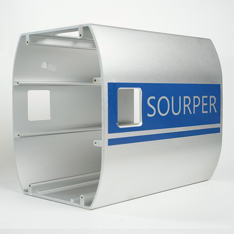
Machining and Surface Treatment: Enhancing high-performance heat dissipation housing for ESS
To achieve a truly high-performance heat dissipation housing for ESS, the die-cast unit often undergoes secondary treatments. Precision machining is used to create perfectly flat interfaces for battery modules or cooling plates, minimizing contact resistance—the thermal enemy of efficiency. Surface treatments, such as anodizing or specialized coatings, are then applied to further enhance performance. Anodizing increases the thickness of the naturally occurring oxide layer, primarily for corrosion resistance and electrical insulation. Crucially for passive cooling, certain surface finishes, particularly those that are black or dark, can significantly increase the emissivity ($\epsilon$) of the housing, thereby maximizing heat loss through thermal radiation. While this gain is modest compared to conduction, every watt of heat dissipated contributes to a lower operating temperature and a longer system life.
| Treatment Type | Primary Benefit | Thermal Impact |
| Precision Machining | Achieving flatness ($\sim 0.05\ \text{mm}$) | Minimizes Contact Thermal Resistance |
| Anodizing (Clear/Color) | Corrosion/Abrasion Resistance | Provides Electrical Isolation (Insulation) |
| Black Coating/Paint | Aesthetics/Enhanced Emissivity | Maximizes Heat Dissipation via Radiation |
Advanced Cooling Integration: optimizing liquid cooling plates for energy storage systems
For large-scale, utility-grade ESS deployments where high thermal loads are sustained over long periods, active liquid cooling becomes essential. This is facilitated by optimizing liquid cooling plates for energy storage systems which are typically integrated directly into the base of the Energy Storage Heat Sinks Housing. These plates contain serpentine channels through which a circulating dielectric fluid or a water/glycol mix removes heat from the battery cells by convection. The effectiveness of this system is highly dependent on the design of the plates themselves—specifically, the geometry of the internal flow channels. Optimal design ensures that the coolant velocity is sufficient to achieve a high heat transfer coefficient without incurring excessive pumping power (pressure drop) or flow path restrictions. The goal is to maximize the heat extracted per unit of pumping power, thereby improving the overall system efficiency (COP, or Coefficient of Performance) and reducing the system's own parasitic energy consumption. This often involves Computational Fluid Dynamics (CFD) modeling to simulate heat flow and pressure profiles before manufacturing.
- High Thermal Capacity: Liquid coolants have a much higher specific heat capacity than air, allowing them to carry away significantly more heat per unit volume.
- Uniform Temperature: Properly designed flow channels achieve superior temperature uniformity across the battery module compared to forced air systems.
- System Miniaturization: Liquid cooling allows for tighter packing of battery cells, increasing the overall energy density of the ESS unit.
Plate Design Factors: Flow Path and Material Thickness
Two critical parameters for optimizing liquid cooling plates for energy storage systems are the flow path design and the thickness of the plate material separating the coolant from the battery cell. A well-designed flow path (e.g., parallel, serpentine, or multi-pass) ensures even distribution of the coolant velocity and temperature across the entire surface area. Too slow a flow leads to localized heating, while too fast a flow leads to high-pressure drop and energy waste. Similarly, the plate material thickness must be minimized to reduce the thermal resistance between the heat source (battery tab/bottom) and the heat sink (coolant). Thinner plates, however, require high-precision manufacturing techniques, such as friction stir welding or vacuum brazing, to ensure integrity and prevent leakage—a critical safety concern. Balancing the thermal benefits of thin material against the mechanical requirements and manufacturing cost is key to the plate's final design.
- Pressure Drop: The resistance to fluid flow; a lower pressure drop requires less pump energy.
- Wetted Surface Area: Maximizing the contact area between the coolant and the plate surface enhances convective heat transfer.
Liquid Cooling vs. Air Cooling: Performance Metrics
When selecting a cooling strategy, ESS designers weigh the superior performance of liquid cooling against the simplicity and lower initial cost of air cooling. Liquid cooling excels at maintaining a tighter temperature range, which is critical for extending the life of high-power cells. It also has a much higher heat rejection capacity, making it the only viable choice for systems with high C-rates (charge/discharge current relative to capacity). Conversely, forced-air cooling, while simple, suffers from poor temperature uniformity and low heat transfer coefficient, meaning it is only suitable for low-power or low-duty cycle ESS applications. The initial cost of implementing a liquid cooling loop, including the plates, pumps, hoses, and manifold, is substantially higher than a simple fan system, which is why the decision is driven entirely by the required performance metrics.
| Metric | Liquid Cooling System | Forced-Air Cooling System |
| Heat Transfer Coefficient | High (Water $\sim 1000\ \text{W/m}^2\cdot\text{K}$) | Low (Air $\sim 10\ \text{W/m}^2\cdot\text{K}$) |
| Temperature Uniformity | Excellent ($\Delta T < 2^\circ\text{C}$ typically) | Fair to Poor ($\Delta T > 5^\circ\text{C}$) |
| Maintenance Needs | Moderate (Fluid checks, pump maintenance) | Low (Filter cleaning, fan replacement) |
Strategic Selection: Choosing cost-effective energy storage housing with integrated cooling
The ultimate challenge for ESS manufacturers is delivering a cost-effective energy storage housing with integrated cooling that does not compromise on performance or safety. Achieving cost-effectiveness is a complex trade-off that goes beyond the simple unit price of the Energy Storage Heat Sinks Housing. It involves evaluating the entire lifecycle cost, including manufacturing scalability, potential warranty costs associated with thermal failures, and the operational expense (OpEx) of the cooling system's parasitic load. For example, a slightly more expensive die-cast aluminum housing that facilitates superior passive cooling may eliminate the need for an active fan system, reducing power consumption and maintenance costs over a 15-year service life. This strategic selection process requires manufacturers to move away from simplistic component pricing and adopt a Total Cost of Ownership (TCO) model, where thermal efficiency is directly quantified as a saving in battery replacement or a gain in usable capacity.
- Manufacturing Optimization: Designing the enclosure for single-pass die-casting or extrusion can drastically reduce processing time and material waste.
- Standardization: Using standard heat sink profiles and components where possible reduces custom tooling costs and streamlines the supply chain.
Assessing Total Cost of Ownership (TCO) for Cooling Housings
The TCO analysis for a cost-effective energy storage housing with integrated cooling must factor in four key financial elements over the product lifecycle. Firstly, the Initial Capital Expenditure (CapEx), which includes the material and manufacturing cost of the housing and cooling system. Secondly, the Operational Expenditure (OpEx), which covers the energy consumed by the cooling system (pumps, fans, chillers) and the maintenance labor/parts. Thirdly, the replacement cost for battery modules, which is directly mitigated by effective cooling. Lastly, the financial penalty associated with downtime or system failure, which is reduced by a more reliable thermal design. A high-efficiency, yet more expensive, initial housing will often lead to a lower TCO due to reduced OpEx and a longer, more reliable battery life. This long-term perspective is vital for securing competitive advantage in the rapidly evolving ESS market.
- Battery Lifespan: A 10% increase in battery life due to superior cooling can offset a significantly higher initial housing cost.
- Energy Efficiency: Reducing the parasitic load of the cooling system directly contributes to more net energy being delivered to the grid or customer.
Future Trends in Integrated Energy Storage Heat Sinks Housing Design
The future of Energy Storage Heat Sinks Housing is moving toward highly integrated, multifunctional components. We anticipate a shift toward seamless integration of structural, thermal, and electrical functions within the enclosure. This includes the use of advanced composite materials that are structurally robust while offering tailor-made thermal characteristics, or additive manufacturing (3D printing) to create complex, internal lattice structures that maximize heat exchange surface area. Another major trend is the integration of phase-change materials (PCM) directly within the housing structure, offering a passive, temporary buffer against short-term thermal spikes. These innovations aim to make the cooling process entirely localized and autonomous, minimizing the reliance on external, energy-consuming active cooling components, thus making the entire ESS system lighter, more compact, and inherently safer.
- PCM Integration: Utilizing Phase Change Materials to absorb heat during rapid discharge/charge cycles, delaying temperature rise.
- Smart Materials: Developing enclosures with embedded sensors and dynamically adjustable thermal properties.
FAQ
What is the primary difference between a standard enclosure and an Energy Storage Heat Sinks Housing?
The core difference lies in function and material composition. A standard enclosure provides mechanical protection and environmental sealing, but is typically made of steel or lower-grade aluminum with moderate thermal conductivity. An Energy Storage Heat Sinks Housing, by definition, is designed to be an active thermal component. It is typically manufactured from high-thermal-conductivity aluminum (often die-cast) with complex, integrated features—such as cooling fins, internal ribs, or channels—engineered to maximize the transfer of heat away from the battery cells. Its design is governed by thermal efficiency metrics (e.g., Watts per Kelvin), not just structural strength, making it a critical part of thermal management solutions for battery energy storage.
How does choosing die-casting aluminum enclosures for ESS cooling impact overall system weight?
Choosing die-casting aluminum enclosures for ESS cooling provides an optimal balance for weight management in large-scale systems. While aluminum is denser than plastic, its superior thermal and mechanical properties allow the wall thickness to be significantly reduced compared to less conductive metals like steel, resulting in a net weight reduction. Furthermore, the die-casting process allows for complex ribbing and lattice structures that add immense strength without adding unnecessary mass. This is crucial for maximizing the energy density of the ESS, as every kilogram saved in the housing can be dedicated to battery cells, leading to a more high-performance heat dissipation housing for ESS overall.
Are there inherent safety advantages to optimizing liquid cooling plates for energy storage systems?
Yes, significant safety advantages exist. By optimizing liquid cooling plates for energy storage systems, engineers can achieve far tighter temperature control and uniformity across the battery pack. This uniformity is the primary defense against localized hot spots that can trigger thermal runaway—the most serious safety hazard in lithium-ion systems. A liquid cooling system can also be designed to isolate modules. In the event of an internal thermal event, the circulating non-flammable or dielectric fluid can rapidly draw heat away from the affected cell cluster, or the system can quickly isolate and shut down the affected loop, significantly limiting the propagation risk and making the entire solution a more cost-effective energy storage housing with integrated cooling from a risk mitigation standpoint.