English
 Español
Content
- 1 Understanding the Core Function of a Micro Motor Shell
- 2 Selecting the Optimal Material for Your Micro Motor Casing
- 3 Key Design Considerations for High-Performance Motor Housings
- 4 Exploring the Various Types of Precision Micro Motor Enclosures
- 5 A Guide to Custom Micro Motor Shell Manufacturing Processes
- 6 Maintenance and Troubleshooting for Durable Micro Motor Casings
Understanding the Core Function of a Micro Motor Shell
At the heart of countless miniature devices lies the micro motor, a marvel of engineering that converts electrical energy into precise mechanical motion. While the internal components like the armature, magnets, and brushes often receive the most attention, the external casing plays an equally critical role. The micro motor shell is far more than a simple cover; it is a multifunctional component that ensures the motor's integrity, performance, and longevity. This section delves into the fundamental purposes of the shell, establishing why its design and material selection are paramount for any application.
Primary Roles and Responsibilities
The shell of a micro motor is tasked with a diverse set of responsibilities that directly impact the motor's operation. Firstly, it provides crucial structural support and housing, maintaining the precise alignment of internal components. Any misalignment, even on a microscopic scale, can lead to increased friction, vibration, and premature failure. Secondly, the shell acts as the first line of defense against external contaminants. Dust, moisture, and other particulate matter can be devastating to the delicate internals of a motor, leading to short circuits, blockages, and corrosion. A well-sealed shell prevents these elements from entering the system.
Furthermore, the shell plays a vital role in thermal management. During operation, motors generate heat due to electrical resistance and mechanical friction. If this heat is not effectively dissipated, it can lead to overheating, which degrades insulation, demagnetizes permanent magnets, and ultimately causes motor burnout. The shell serves as a heat sink, transferring thermal energy away from the core and into the surrounding environment. Finally, the shell provides electromagnetic shielding, containing the motor's magnetic field to prevent interference with nearby sensitive electronic components and protecting the motor from external electromagnetic noise.
The Impact of Shell Design on Overall Performance
The design of the shell is inextricably linked to the motor's overall performance characteristics. Its size and weight directly contribute to the motor's inertia and, consequently, its acceleration and deceleration responsiveness. The material's thermal conductivity determines how efficiently heat is dissipated, affecting the motor's continuous duty cycle and maximum torque output. The structural rigidity influences the motor's ability to dampen vibrations and reduce acoustic noise, a critical factor in applications like medical devices or audio equipment. Therefore, selecting the right shell is not an afterthought but a fundamental part of the motor design process that dictates performance boundaries.
Selecting the Optimal Material for Your Micro Motor Casing
Choosing the right material for a micro motor casing is a complex decision that balances mechanical, thermal, electrical, and economic factors. The material dictates the motor's weight, durability, heat dissipation capabilities, and cost. There is no one-size-fits-all solution; the optimal choice is entirely dependent on the specific demands of the application. This section explores the most common materials used, comparing their properties to guide you toward an informed selection.
Common Materials and Their Properties
The landscape of materials for micro motor shells is dominated by metals and plastics, each with their own distinct advantages and limitations.
Metallic Alloys: Aluminum and Stainless Steel
Metallic casings, particularly those made from aluminum alloys and stainless steel, are renowned for their excellent strength and heat dissipation.
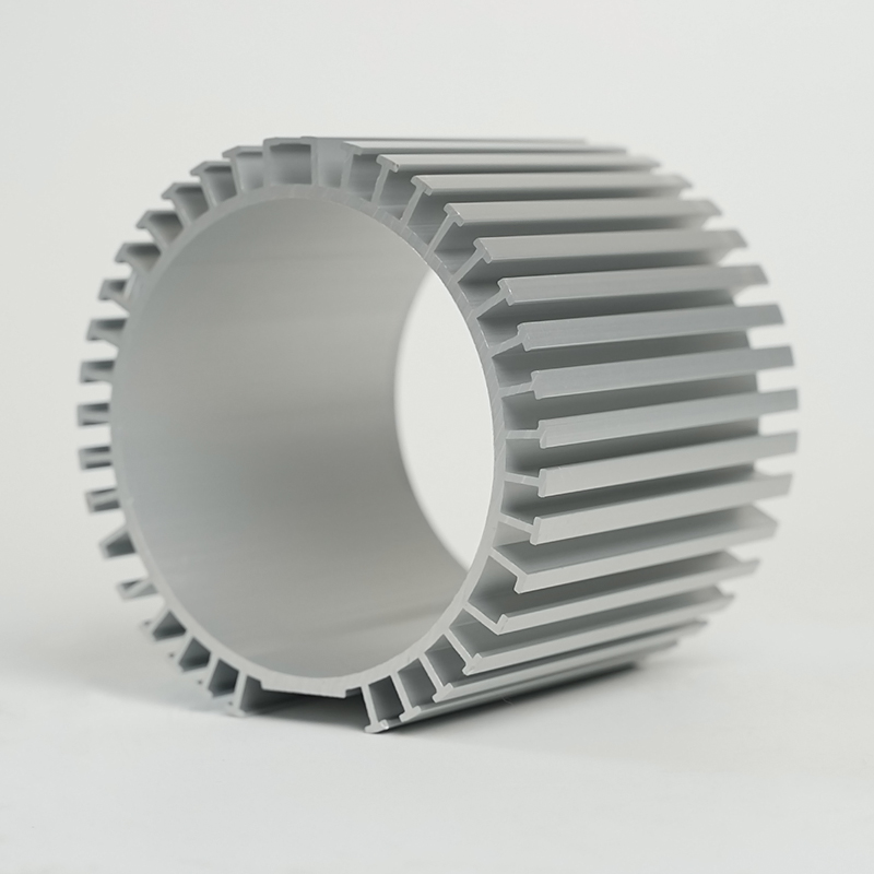
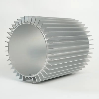
- Aluminum Alloys: Prized for their high thermal conductivity, low density (making them lightweight), and good corrosion resistance. Aluminum is often used in applications where heat management is a priority, such as in high-speed or continuous-duty motors. However, it is generally more expensive than plastic and can be more challenging to manufacture into complex shapes.
- Stainless Steel: Offers superior mechanical strength, hardness, and exceptional corrosion resistance. It is the material of choice for motors operating in harsh, corrosive environments or those requiring extreme structural integrity. The trade-offs are its significantly higher weight and lower thermal conductivity compared to aluminum.
Engineering Plastics and Composites
Advanced polymers and composite materials have become increasingly popular due to their versatility, cost-effectiveness, and unique properties.
- PBT (Polybutylene Terephthalate) and Nylon: These thermoplastics offer good electrical insulation, high mechanical strength, and decent chemical resistance. They are lightweight, inexpensive to mass-produce via injection molding, and can be easily integrated with other components. Their primary drawback is lower thermal conductivity, which can be a limiting factor for high-power applications.
- PPS (Polyphenylene Sulfide): A high-performance plastic known for its exceptional thermal stability, chemical resistance, and inherent flame retardancy. It is suitable for motors that face high temperatures and aggressive chemical environments.
Material Comparison Table
The following table provides a clear, side-by-side comparison of the key properties of these common materials, illustrating the inherent trade-offs designers must make.
| Material | Thermal Conductivity | Density (Weight) | Corrosion Resistance | Cost | Ideal Application |
|---|---|---|---|---|---|
| Aluminum Alloy | High | Low | Good | Medium-High | High-speed drones, precision instruments |
| Stainless Steel | Medium | High | Excellent | High | Medical devices, automotive systems |
| PBT/Nylon | Low | Very Low | Fair to Good | Low | Consumer electronics, household appliances |
| PPS | Low | Very Low | Excellent | Medium | Under-hood automotive, chemical pumps |
As the table demonstrates, aluminum provides the best thermal performance but at a higher cost and with moderate weight. Stainless steel offers unparalleled durability in tough conditions but is heavy. Plastics are lightweight and cheap but poor at dissipating heat. The choice ultimately hinges on which property is most critical for the motor's intended use.
Key Design Considerations for High-Performance Motor Housings
Designing a high-performance micro motor housing requires a meticulous approach that goes beyond simply enclosing the components. It involves a holistic engineering process focused on optimizing for thermal management, structural mechanics, manufacturability, and integration. A high-performance housing is what separates a reliable, efficient, and long-lasting motor from a mediocre one. This section breaks down the critical factors that engineers must address during the design phase.
Thermal Management Strategies
Effective heat dissipation is arguably the most crucial aspect of designing for high performance. Excessive heat is the primary enemy of motor longevity. Several strategies can be employed through the housing design to combat this.
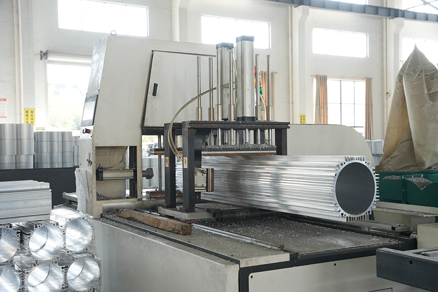
- Integrated Heat Sinks: Designing the external surface of the housing with fins or ridges significantly increases the surface area exposed to the air, dramatically improving convective heat transfer. This is a common feature in aluminum housings for brushless motors.
- Thermal Interface Materials (TIMs): Using thermally conductive greases or pads between the internal motor core and the housing shell ensures efficient thermal transfer from the heat source to the heat-dissipating shell.
- Material Selection: As previously discussed, selecting a material with high thermal conductivity, like aluminum, is fundamental for applications with high thermal loads.
- Airflow Management: The housing design can incorporate vents or channels to guide cooling airflow over the motor. However, this must be balanced against the need for ingress protection (e.g., IP ratings).
Structural Integrity and Vibration Damping
A housing must be rigid enough to prevent deformation under load, which would misalign internal components and cause failure. This involves performing structural analysis (like Finite Element Analysis or FEA) to identify and reinforce weak points. Simultaneously, the housing must effectively dampen vibrations generated by the motor itself. Excessive vibration leads to noise, wear on components, and failure of solder joints. Design techniques include:
- Adding strategic ribs to increase stiffness without adding substantial weight.
- Incorporating vibration-damping materials or mounts between the motor and the external structure.
- Ensuring a precise fit between components to avoid rattles and micro-movements.
Manufacturing Techniques and Tolerances
The chosen manufacturing process is dictated by the material and the complexity of the design. Metal housings are typically die-cast or machined, allowing for high precision and excellent thermal properties but at a higher cost. Plastic housings are almost exclusively injection molded, which is highly cost-effective for high volumes and allows for incredibly complex and integrated shapes. Regardless of the method, maintaining tight tolerances is critical for ensuring proper bearing alignment, gear meshing (if applicable), and overall assembly consistency. A design for manufacturability (DFM) approach is essential to avoid features that are impossible or prohibitively expensive to produce.
Exploring the Various Types of Precision Micro Motor Enclosures
The world of precision micro motor enclosures is diverse, with different designs tailored to meet specific operational and environmental needs. The type of enclosure directly affects the motor's protection level, cooling method, and overall suitability for an application. Understanding these types is crucial for selecting the right motor for the job. This section explores the most common enclosure types, from open-frame to fully sealed units.
Open Frame Enclosures
An open frame enclosure, as the name suggests, offers the least amount of protection. It typically consists of a basic structural frame that holds the motor components in place but exposes the armature and windings to the open air.
- Advantages: The primary advantage is exceptional cooling due to maximum exposure to ambient air. This design is also the simplest and least expensive to manufacture.
- Disadvantages: It provides virtually no protection against dust, moisture, or physical contact. These motors are highly susceptible to damage from foreign objects and are unsuitable for any environment that is not clean and dry.
- Applications: Primarily used in laboratory settings, prototype development, or within larger enclosed systems where the external device itself provides the necessary protection.
Totally Enclosed Non-Ventilated (TENV) Enclosures
TENV enclosures represent a significant step up in protection. The motor is completely sealed within a shell, preventing the free exchange of air between the inside and outside of the motor.
- Advantages: Offers excellent protection against dust, dirt, and minor moisture exposure (e.g., splashing). It is more robust than an open frame design.
- Disadvantages: Heat dissipation is less efficient as it relies solely on conduction through the shell and convection from the outer surface. This can limit the motor's power density and continuous duty cycle.
- Applications: Widely used in appliances, pumps, fans, and other applications where the operating environment may contain airborne contaminants.
Totally Enclosed Fan Cooled (TEFC) and Waterproof Enclosures
For more demanding applications, even more specialized enclosures are required.
- TEFC: This design is similar to TENV but includes an external fan mounted on the motor shaft. This fan blows air over the exterior of the housing, greatly enhancing convective heat transfer and allowing for higher power output than a standard TENV motor.
- Waterproof/IP67+ Enclosures: These are highly specialized TENV enclosures designed with advanced sealing techniques (e.g., gaskets, O-rings, sealed connectors) to withstand immersion in water or exposure to high-pressure jets. They are characterized by their high Ingress Protection (IP) ratings, such as IP67 or IP68.
The progression from open frame to waterproof enclosures shows a clear trade-off: increasing protection almost always comes with a compromise in thermal performance and an increase in cost and complexity. The selection must be based on a thorough understanding of the operational environment.
A Guide to Custom Micro Motor Shell Manufacturing Processes
When off-the-shelf solutions fail to meet specific application requirements, the path of custom micro motor shell manufacturing becomes necessary. This process involves creating a unique housing tailored to exact dimensional, material, and performance specifications. Engaging in custom manufacturing allows for optimization that is impossible with standard parts, but it requires a deep understanding of the available processes and their implications. This guide walks through the primary manufacturing routes for custom shells.
Injection Molding for Plastic Shells
Injection molding is the dominant process for mass-producing plastic motor housings. It involves heating plastic pellets until molten and then injecting them under high pressure into a precision-machined metal mold cavity.
Stages of Injection Molding:
- Tooling Design and Manufacturing: The first and most critical step is creating the mold (or "tool"). This is a complex, expensive, and time-consuming process involving CNC machining of hardened steel or aluminum. The design must account for material shrinkage, cooling channels, and ejection mechanisms.
- The Molding Cycle: The cycle involves clamping the mold shut, injecting the molten plastic, holding pressure to pack the cavity, cooling the part, opening the mold, and ejecting the finished part. This cycle can take seconds to minutes.
- Post-Processing: After ejection, parts may require trimming of excess plastic (flash) and any secondary operations like tapping holes or adding inserts.
Advantages: Extremely high production rates, excellent repeatability, low per-part cost at high volumes, and ability to create complex geometries with high precision.
Disadvantages: Exceptionally high initial tooling cost, long lead time for tool manufacturing, and economic infeasibility for low-volume production.
Die Casting and CNC Machining for Metal Shells
For metal housings, the two main processes are die casting and CNC machining.
- Die Casting: Similar in principle to injection molding but for metals. Molten metal (e.g., aluminum or zinc alloy) is forced under high pressure into a steel mold. It is ideal for producing high volumes of complex, thin-walled metal parts with good surface finish and dimensional stability. While tooling is expensive, the per-part cost is low for high volumes.
- CNC Machining: A subtractive process where a solid block of metal (or plastic) is shaped by computer-controlled cutting tools that remove material. This process is incredibly versatile and precise, capable of producing parts with extremely tight tolerances and complex features. It is ideal for prototypes, low-volume production, and parts that require higher strength than castings. The main disadvantages are higher per-part cost (due to waste material and longer cycle times) and some geometric limitations compared to casting.
Choosing the Right Process
The decision between these processes is primarily driven by three factors: volume, material, and complexity.
- Volume: High volume (10,000+ parts) favors injection molding or die casting despite the high tooling cost. Low volume (1 - 1,000 parts) makes CNC machining the default choice.
- Material: The desired material often dictates the process. Most plastics are injection molded, while metals are die-cast or machined.
- Complexity and Precision: Highly complex shapes are best achieved through molding or casting. Parts requiring the highest possible precision and strength are often machined.
Navigating custom manufacturing requires close collaboration with experienced manufacturing engineers to select the most cost-effective and technically suitable process for the application.
Maintenance and Troubleshooting for Durable Micro Motor Casings
Ensuring the long-term health of a micro motor involves proactive maintenance and astute troubleshooting of its external protection system. A durable micro motor casing is designed to last, but it is not indestructible. Understanding how to care for it and identify signs of failure can prevent catastrophic motor breakdowns and extend service life significantly. This final section provides a practical guide for users and technicians.
Routine Inspection and Preventive Maintenance
A regular maintenance schedule is the best defense against unexpected failures. The focus should be on the external condition and performance of the motor.
- Visual Inspection: Regularly check the casing for any signs of physical damage, such as cracks, dents, or deep scratches. These can compromise structural integrity and protection levels. Look for signs of corrosion, especially on metal casings, which can weaken the material and lead to holes.
- Cleaning: Keep the motor casing clean and free of debris. For TENV and TEFC motors, ensure that cooling fins and fan blades (if present) are not clogged with dirt, as this will severely impair heat dissipation. Use a soft brush or low-pressure compressed air, taking care not to damage any components.
- Check Seals and Gaskets: For motors rated as waterproof or dustproof, periodically inspect the integrity of seals, gaskets, and cable glands. These materials can degrade over time due to heat, ozone, or mechanical stress, breaking the seal.
- Thermal Monitoring: Use an infrared thermometer or thermal camera to periodically check the motor's operating temperature. A gradual increase in temperature over time can indicate that the housing's cooling fins are clogged, the internal thermal path is degraded, or the bearing is failing, generating extra heat.
Common Issues and Diagnostic Steps
When a problem is suspected, a systematic approach to diagnosis is key.
- Overheating: If the motor is overheating, the issue could be external (clogged cooling fins, operating in a high ambient temperature) or internal (bearing wear, electrical fault). First, check and clean the exterior of the housing. If the problem persists, the fault is likely internal.
- Physical Damage: A cracked or dented casing must be replaced. Even a small crack can allow harmful contaminants to enter, leading to internal corrosion or electrical shorts.
- Noise and Vibration: While often an internal issue, excessive noise or vibration can sometimes be caused by a loose housing mount or a foreign object impacting the external fan (on a TEFC motor). Ensure all mounting hardware is tight and the external airflow path is clear.
- Loss of Performance: If the motor seems less powerful or struggles under load, consider that overheating due to poor heat dissipation from the casing could be causing the internal electronics to derate (reduce power) to protect themselves.
By integrating these maintenance and troubleshooting practices, the integrity of the micro motor casing can be preserved, ensuring it continues to provide reliable protection for the sensitive components within, thereby maximizing the investment in the equipment.