English
 Español
Content
Maximizing Heat Flow in Aluminum Electric Motor Casings
When engineers discuss aluminum electric motor casing heat dissipation, they are really talking about managing a chain of thermal resistances: from copper windings or stator laminations into the yoke and mounting features, through the casing wall, across the outer surface, and finally into the surrounding air or liquid. Any weak link in this chain raises hotspot temperatures and compresses performance margins. Aluminum’s high thermal conductivity compared with ferrous housings makes it an obvious first choice, but realizing that advantage depends on thoughtful material selection, contact design, and surface engineering. The goal is not simply moving heat; it is moving heat predictably while controlling weight, manufacturability, and cost.
Thermal Pathways Inside the Housing
Inside the casing, heat leaves the stator teeth and yoke by conduction and crosses into the housing via press fits, bonding interfaces, or potting compounds. A continuous, highly loaded contact interface reduces contact resistance. Practical steps include tightly toleranced press fits, thin and uniform interface materials, and deliberate clamping pressure that avoids distortion. Where potting or gap filler is necessary, choose materials balancing conductivity with viscosity so they wet micro-asperities without trapping air. Designers often improve conduction by extending the stator teeth or adding copper shunts that shorten the path length. Because aluminum expands more than steel, differential expansion at operating temperatures must be considered; too much interference at assembly can become too little during hot operation, degrading thermal transfer just when it is most needed.
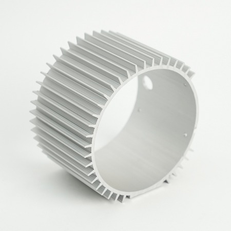
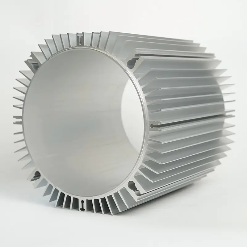
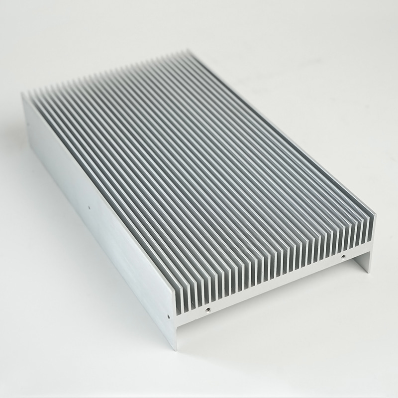
Fin Geometry, Airflow, and Surface Treatments
Outside the casing, convection dominates. Straight fins are simple and cost-effective, but louvered or wavy fins disturb boundary layers and can outperform in low-speed airflow. Fin spacing should account for fouling risk and manufacturing draft angles. Surface treatments can be counterintuitive: a micro-roughened surface may increase convective heat transfer by tripping turbulence even as it slightly reduces conductivity, and a dark anodic layer increases emissivity, which matters wherever radiation is non-negligible. If the motor lives inside a shroud or under-hood environment, ducted airflow with known velocity profiles is more reliable than relying on incidental flow. When dust or insects are likely, choose thicker fins with wider spacing to preserve performance over time.
Material Grades and Thermal Conductivity
Different aluminum grades trade conductivity against castability and strength. High-silicon die-casting alloys flow beautifully and fill thin fins, but their thermal conductivity is lower than wrought grades. In contrast, wrought 6xxx series extrusions offer excellent conductivity and machinability, though they may demand more machining to reach complex geometries. Because material choice interacts with process, decisions should weigh thermal gains against tooling and piece-part costs. The following comparisons put numbers in context before the full table summary.
- Aluminum typically conducts heat several times better than stainless steels at room temperature, which can translate to smaller temperature rise for the same heat flux.
- Within aluminum families, lower silicon or wrought alloys generally conduct better than high-silicon die-casting alloys, at the expense of casting thin walls as easily.
- Magnesium is lighter but usually conducts heat less effectively than common aluminum grades and can complicate corrosion management.
| Material | Thermal Conductivity (W/m·K) | Density (g/cm³) | Notes |
|---|---|---|---|
| Aluminum (wrought 6061/6063) | ~170–210 | ~2.70 | High conductivity; requires machining for complex shapes |
| Aluminum (high-Si die-cast, e.g., ADC12/A380 type) | ~90–130 | ~2.70 | Excellent castability for thin fins; moderate conductivity |
| Magnesium alloys | ~60–100 | ~1.80 | Lighter; more complex corrosion and flammability considerations |
| Cast iron | ~45–60 | ~7.20 | Heavy; lower thermal performance vs. aluminum |
| Stainless steel | ~14–20 | ~8.00 | Poor thermal conductor; used only when required structurally |
Testing Methods and Design Feedback Loops
Thermal models accelerate learning, but they must be anchored by measurement. Infrared thermography reveals hotspots around bearing shoulders and rib intersections. Calibrated heat-soak tests with known loads validate CFD, while thermal shock cycling exposes interface degradation over life. The most effective programs treat thermal benchmarking as a routine gate in design releases, not a special event. This systems approach is what ultimately turns the phrase aluminum electric motor casing heat dissipation from a search query into a competitive advantage in the field.
Choosing a Production Route and Evaluating Partners
Selecting a process and vetting die cast aluminum motor housing suppliers is a multi-variable exercise. Die casting excels at high volumes with thin walls and integrated fins; sand casting offers flexibility and lower tooling investment at the cost of thicker sections; extrusion plus CNC machining provides superb surface finish and conductivity for simpler geometries; and permanent-mold casting sits between sand and die casting for medium runs. The right choice balances geometry, tolerance, cosmetics, and total cost of ownership. When two routes appear viable, compare them in sentences first and confirm with a tabulated scorecard so trade-offs are transparent to engineering, quality, and sourcing teams alike.
Die Casting vs. Sand Casting vs. Extrusion + CNC
Die casting usually wins where you need many thin fins and consistent wall thickness with tight repeatability. Sand casting, while coarser, supports large housings and quick design iterations without high upfront tools. Extrusion + CNC machining makes sense for cylindrical or prismatic shells where linear fins or simple ducts can be cut from stock; it also preserves higher thermal conductivity of wrought aluminum. Investment casting can achieve fine detail but often loses ground on cost for larger parts. Because surface finish affects sealing, painting, and thermal emissivity, consider how much machining or post-processing each route needs to hit performance and cosmetic targets.
| Process | Typical Wall | Surface Finish (Ra) | Tooling Cost | MOQ Suitability | Typical Tolerance |
|---|---|---|---|---|---|
| High-pressure die casting | 1.5–3.0 mm | ~1.6–3.2 µm | High | High volume | ±0.1–0.3 mm before machining |
| Sand casting | 4–8 mm | ~6.3–12.5 µm | Low | Low to medium | ±0.5–1.0 mm before machining |
| Permanent-mold casting | 3–5 mm | ~3.2–6.3 µm | Medium | Medium | ±0.2–0.5 mm before machining |
| Extrusion + CNC machining | Depends on profile | ~0.8–1.6 µm (machined) | Low (die) to Medium | Low to high | ±0.02–0.1 mm on critical features |
Tooling, Lead Time, and Total Cost of Ownership
Total cost of ownership (TCO) combines amortized tooling, piece-part price, scrap, freight, and quality risks. Die casting has higher tooling but low cycle time; sand casting reverses that. If annual volume is uncertain, starting with sand casting or extrusion can de-risk the program and provide real demand data before committing to hard tooling. Conversely, when the launch forecast is firm and the geometry suits it, moving early to die casting can pay back tooling quickly by shrinking cycle time and machining content. Supplier location influences logistics risk and lead time; dual-sourcing with common inspection plans and interchangeable tools can stabilize supply.
Quality Systems and Supplier Assessment
When screening die cast aluminum motor housing suppliers, look beyond nominal capabilities. Request process-flow diagrams, PFMEA examples, and statistical capability data on similar housings. Review metallographic reports for porosity and cold-shut control, and ask how gating/overflow strategies reduce gas entrapment in thin fins. Validate that coordinate-measuring equipment and pressure-test rigs match your inspection plan. A mature supplier will welcome a joint DFM/DFMEA workshop that reduces risk before steel is cut.
Environmental Protection and Sealing Strategy
Designing a corrosion resistant aluminum motor enclosure IP65 means thinking holistically about water, dust, chemicals, temperature cycling, and galvanic couples. IP65 denotes dust-tight construction and protection from water jets, but passing a lab test once is not the same as thriving over years in the field. Real environments combine salt spray, conductive dust, oils, and thermal gradients that pump moisture through micro-gaps. To succeed, sealing features must be generous, coatings must be compatible, and dissimilar metals must be isolated. Because corrosion is a system problem, many failures trace back to interfaces—fasteners, bosses, and covers—rather than the bulk aluminum itself.
IP Ratings, Gaskets, and Breathers
Start by choosing gasket geometry that maintains compression after aging: sponge closed-cell elastomers for low water ingress, or molded profiles for robust flange engagement. Target compression ranges that account for tolerance stack-ups; use compression limiters in plastic covers to avoid over-squeezing. Where the casing heats and cools, a membrane breather equalizes pressure and reduces the tendency to pull moisture past seals. Cable glands and conduit entries must match ingress targets; even one under-spec gland can degrade an otherwise excellent design.
Coatings, Anodizing, and Corrosion Testing
Uncoated aluminum forms a protective oxide, but chloride-rich environments demand more. Anodizing increases corrosion resistance and surface hardness; powder coating provides a tough, attractive finish; and conversion coatings improve paint adhesion. When parts will be assembled with stainless fasteners, use insulating washers or sealants to mitigate galvanic potential. Validate coating systems with neutral salt spray and cyclic corrosion tests that include crevice coupons representative of real joints, not just flat panels. The best practice is to combine robust sealing with a finish tailored to the environment, then verify with accelerated tests.
| Protection Method | Main Benefit | Typical Use | Notes |
|---|---|---|---|
| Anodizing (Type II/III) | Corrosion & wear resistance | General outdoor, abrasive areas | Higher emissivity can aid cooling; thickness control matters |
| Powder coating | Barrier + aesthetics | Industrial and coastal use | Requires proper pretreatment; watch for edge pull-back |
| Conversion coating | Adhesion promotion | Primer under paint | Thin; used with other coatings |
| Sealing gaskets | Ingress protection | Flanges and covers | Design for compression set and service temperature |
| Breather membranes | Pressure equalization | Rapid temp cycling | Reduces pumping of moisture across seals |
Fasteners, Interfaces, and Dissimilar Metals
Galvanic couples drive many field issues. If stainless fasteners are required, isolate them from the aluminum with captive washers, apply compatible anti-seize, and avoid water-retaining geometries. Where steel brackets bolt to the casing, use sealant in the joint to reduce crevice corrosion. Finally, treat grounding points and paint breaks deliberately so protective systems are not unintentionally compromised. A disciplined approach turns an “IP test pass” into a rugged corrosion resistant aluminum motor enclosure IP65 that thrives in real weather and washdowns.
Mass Reduction for Modern Drivetrains
Electrification places a premium on weight and package efficiency, making the quest for a lightweight aluminum motor casing for EV motors more than a slogan. Lower mass improves vehicle efficiency, broadens thermal headroom, and eases assembly handling. But weight cuts cannot compromise casing stiffness, bearing alignment, or acoustic behavior. The art is to remove grams where structure contributes least, while preserving load paths and thermal performance. Doing this well blends topology optimization, casting-friendly ribbing, and judicious machining that avoids creating stress risers or thin sections vulnerable to porosity.
Structural Topology and Weight Targets
Begin with a stiffness-driven topology: define bearing loads, gearbox reactions, and mounting constraints, then let a solver identify corridors of material that carry most of the stress. Translate the result into castable ribs and webs with uniform wall transitions, generous fillets, and consistent draft. For cylindrical housings, consider integral rib bands that double as heat-spreading rings. Establish weight and stiffness targets early so trade-offs are visible during design reviews rather than discovered during DV testing.
Thermal–Structural Trade-Offs
Weight reduction sometimes conflicts with cooling. Thinner walls reduce conduction area, yet more but thinner fins can restore convective area if casting allows. If CFD shows a hot zone near a mounting boss, a local heat spreader rib may out-perform a global wall-thickness increase. Similarly, a dark, durable coating can raise emissivity and recover some thermal margin without structural penalty. The trick is to combine several modest improvements rather than rely on one heavyweight fix. When a water-glycol jacket is feasible, integrated channels can shift the thermal regime entirely, enabling lower wall thickness without overheating.
NVH, Stiffness, and Integration
Light parts can ring. To keep a lightweight aluminum motor casing for EV motors quiet, tune rib spacing and thickness to break up panel modes, and use asymmetric rib patterns where feasible. Integration—such as combining rotor-end shields, inverter mounts, or coolant manifolds—removes brackets and fasteners that add weight and complexity. Compare two options in words, then confirm with a simple table: an integrated housing might save 8–12% mass and ten fasteners, while a modular approach may simplify service at slight weight cost. Make decisions in the context of assembly strategy and field repairability, not weight alone.
| Design Approach | Mass Impact | Thermal Impact | Serviceability | Notes |
|---|---|---|---|---|
| Thin walls + many fins | Lower mass | High convective area | Neutral | Requires capable casting to avoid porosity |
| Integrated coolant jacket | Moderate mass | Excellent heat rejection | More complex | Great for sustained high loads |
| Modular brackets | Higher mass | Neutral | Easier to service | Useful when options vary by model |
Precision Machining and Verification
Turning a rough casting into a finished component hinges on precision—captured by the phrase CNC machined aluminum motor casing tolerance 0.01mm. While not every feature demands ten-micron control, bearing bores and mating faces often do. Achieving this requires more than capable machines; it depends on datum strategy, stable fixturing, thermal control, and process capability monitoring. Think of machining as the last chance to align mechanical, thermal, and sealing performance with the design intent.
GD&T for Bearing Bores and Fits
Define datums that reflect how the casing is constrained in service. Concentricity or position of bearing bores should reference the mounting face and the opposite bore to preserve rotor alignment. Circularity and cylindricity at the few-micron level may be necessary to protect bearing life. Flatness on covers and gear interfaces supports gasket compression and gear mesh. Rather than over-tighten every tolerance, concentrate precision at the features that control system behavior and allow generous tolerances elsewhere to reduce cost.
Fixturing, Process Capability, and Inspection
Holding a thin-walled casting without distortion is a craft. Use form-fitting nests and vacuum where appropriate, and control clamping forces to avoid ovalizing bores. Stage machining so heavy stock removal occurs before precision features. Coolant temperature and machine warm-up matter when chasing CNC machined aluminum motor casing tolerance 0.01mm; without thermal stability, measurements drift and capability suffers. Verify critical characteristics with CMMs and air gauges, and monitor with SPC so trends are caught before parts escape. A capable process should demonstrate Cp/Cpk > 1.33 on safety-critical dimensions, with clear reaction plans when control charts signal out-of-control conditions.
Documentation, SPC, and Release Criteria
Robust documentation translates tacit know-how into repeatable outcomes. Control plans should link operations to the characteristics they create and the instruments that verify them. First-article inspection confirms print interpretation, while ongoing audits check that fixturing, cutters, and programs match the approved state. For sealing faces, combine surface finish checks with flatness; for threaded holes, verify location as well as pitch quality. Final leak testing of enclosed volumes and torque-angle verification for inserts complete the package, ensuring the finished casing meets performance, durability, and assembly goals when it leaves the line.
Quick Reference Comparisons
The comparisons below summarize the narrative statements above in a single view to support fast trade-off decisions and cross-functional reviews.
| Topic | Option A | Option B | Sentence Comparison |
|---|---|---|---|
| Material | Wrought aluminum (e.g., 6xxx) | High-Si die-cast aluminum | Wrought grades conduct heat better but need more machining; die-cast grades fill thin fins with lower tooling life risk at volume. |
| Process | Die casting | Sand casting | Die casting provides thinner walls and faster cycles; sand casting offers lower tooling cost and larger, flexible geometries. |
| Cooling | Air-cooled fins | Liquid jacket | Air fins are simpler and lighter; liquid jackets deliver superior steady-state cooling at added complexity and sealing risk. |
| Protection | Anodize | Powder coat | Anodize boosts hardness and emissivity; powder coat adds a thicker barrier layer and broader color/texture options. |
| Machining | Tight GD&T on criticals | Uniform tight tolerances | Targeted tight control hits performance with lower cost; blanket tight tolerances raise scrap without meaningful gains. |