
 English
 Español
Content
- 1 Why Aluminum Has Become the Default Material for Motor Housings
- 2 Alloy Selection: Not All Aluminum Motor Housings Are the Same
- 3 Manufacturing Processes: Die Casting, Sand Casting, and Machining
- 4 Thermal Management Design in Aluminum Motor Housings
- 5 Surface Treatment and Protection
- 6 Key Design Considerations for EV and High-Frequency Motor Housings
- 7 Sourcing and Specification Checklist
Why Aluminum Has Become the Default Material for Motor Housings
Motor housings do far more than contain a rotor and stator. They manage heat, absorb vibration, protect windings from contamination, and in many designs act as a structural load path for the entire drivetrain assembly. For decades, cast iron dominated this application — dense, rigid, proven. But across automotive, industrial, HVAC, robotics, and consumer appliance sectors, aluminum has methodically displaced iron as the first-choice housing material, and the reasons go well beyond weight savings alone.
Aluminum's thermal conductivity — approximately 150–200 W/m·K for common alloys versus 40–50 W/m·K for cast iron — is the single most important functional advantage in motor housing applications. As electric motors are pushed harder and miniaturized further, heat extraction from the stator becomes the primary constraint on power density. An aluminum housing doesn't just hold the motor; it actively conducts heat away from the winding stack and into whatever cooling medium surrounds it, whether that's ambient air, a water jacket, or a finned external surface.
The weight reduction argument is equally compelling. Aluminum alloys used in motor housings typically have densities of 2.6–2.8 g/cm³ versus 7.1–7.2 g/cm³ for cast iron — a 60–65% reduction in mass for equivalent geometry. In electric vehicle drivetrains, where unsprung mass and total powertrain weight are design-critical metrics, this difference directly translates to range and handling performance.
Alloy Selection: Not All Aluminum Motor Housings Are the Same
The term "aluminum motor housing" covers a wide range of material grades with meaningfully different mechanical and thermal properties. Alloy selection is driven by the manufacturing process, service temperature, structural load requirements, and whether the housing will be further machined or anodized.
A380 and ADC12 (Die Casting Alloys)
A380 (North American designation) and ADC12 (Japanese JIS equivalent) are the dominant alloys for high-pressure die-cast motor housings. Both are Al-Si-Cu alloys offering excellent fluidity for complex thin-wall geometries, good dimensional accuracy, and adequate strength after casting. Tensile strength of 317 MPa and yield strength of 159 MPa (A380 as-cast) are sufficient for most industrial motor frames. The tradeoff is moderate corrosion resistance due to copper content — surface treatment is typically required for outdoor or humid environments.
A356 and A357 (Sand Cast and Gravity Die Cast Alloys)
A356 (Al-Si-Mg) is the preferred alloy when higher ductility, better corrosion resistance, or post-cast T6 heat treatment is required. After T6 treatment, A356 achieves tensile strengths of 262–290 MPa with elongations of 5–10% — significantly more ductile than A380 and better suited to housings that experience shock loads or must be welded. A357 adds slightly more magnesium for higher strength. Both alloys are widely used in aerospace-adjacent motor applications and EV traction motor housings where fatigue life under vibration cycling is a design concern.
6061 and 6063 (Wrought Alloys for Machined Housings)
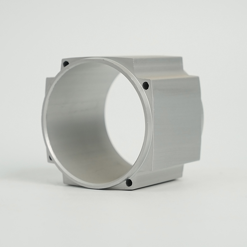
When motor housings are machined from billet or extruded profiles — common in servo motors, precision spindle motors, and small-batch specialty applications — 6061-T6 is the standard choice. Its combination of machinability, 276 MPa yield strength (T6), anodizability, and corrosion resistance makes it the versatile baseline. 6063 is softer and chosen when complex extrusion profiles with integrated cooling fins are more economical than casting.
| Alloy | Process | Tensile Strength | Thermal Conductivity | Best For |
|---|---|---|---|---|
| A380 | HPDC | 317 MPa | 96 W/m·K | High-volume industrial motors |
| A356-T6 | Sand / gravity cast | 262–290 MPa | 151 W/m·K | EV traction, aerospace |
| 6061-T6 | Billet machining | 276 MPa | 167 W/m·K | Servo, precision spindle |
| 6063-T5 | Extrusion | 186 MPa | 201 W/m·K | Finned cooling profiles |
Manufacturing Processes: Die Casting, Sand Casting, and Machining
The production method determines dimensional tolerance, surface finish, wall thickness capability, tooling cost, and unit economics. Understanding the tradeoffs helps in selecting the right process for a given motor design and production volume.
High-Pressure Die Casting (HPDC)
HPDC injects molten aluminum into a steel die under pressures of 10–175 MPa, producing near-net-shape housings with wall thicknesses as thin as 1.5–2.5 mm, excellent surface finish, and tight dimensional repeatability. Cycle times of 30–120 seconds per part make it the most cost-efficient process at volumes above approximately 5,000 units per year. The limitation is porosity — trapped gas during fast fill creates micro-voids that reduce fatigue strength and can leak if the housing must contain pressure (as in liquid-cooled designs). Vacuum-assisted HPDC and squeeze casting are increasingly used to address this in EV motor applications.
Sand Casting and Permanent Mold Casting
Sand casting uses expendable sand molds and is economical for prototyping and low-volume production (under 500 parts/year) with minimal tooling investment. Surface finish and dimensional tolerance are inferior to HPDC, requiring more machining allowance. Permanent mold (gravity die) casting bridges the gap — reusable metal dies, better surface quality than sand, lower porosity than HPDC, and the ability to use heat-treatable alloys like A356-T6 that are difficult to process via HPDC. Commonly used for medium-duty industrial motor frames and specialty traction motors.
CNC Machining from Billet
Billet machining eliminates casting porosity entirely and achieves the tightest dimensional tolerances — critical for precision servo motor housings where bearing bore runout of under 5 μm is required. Material utilization is poor (often 60–80% of the billet becomes chips), making unit costs high, but the process is justified for low-volume, high-precision applications. Five-axis CNC machining enables complex internal cooling channel geometries that would require cores in a casting, and is increasingly used in motorsport and robotics motor housings.
Extrusion with End-Machined Faces
For motors with a consistent cross-sectional profile — particularly brushless DC (BLDC) motors in HVAC fans, pumps, and light industrial drives — extruded aluminum tube or profile stock with integral cooling fins can be cut to length and end-faced. This hybrid approach offers excellent fin geometry for natural convection cooling, low material waste, and short lead times without full die investment. It is constrained to rotationally symmetric or prismatic housing forms.
Thermal Management Design in Aluminum Motor Housings
The housing's thermal architecture is inseparable from motor performance. Heat generated in the stator windings must travel through the lamination stack, across the stator-to-housing interference fit interface, through the housing wall, and into the external cooling medium. Every step in this path has a thermal resistance that limits total power density.
External Fin Cooling
Circumferential or longitudinal fins cast or extruded into the outer housing surface increase the convective surface area available for air cooling. Fin pitch, height, and thickness must be optimized for the airflow conditions — natural convection versus forced-air. Fin height-to-gap ratios above 10:1 are rarely effective in natural convection as airflow between fins becomes restricted. Aluminum's high conductivity ensures fins remain thermally active along their full length, unlike lower-conductivity materials where fins beyond a critical length contribute negligibly to heat transfer.
Integrated Water Jacket
Liquid-cooled motor housings incorporate helical, axial, or annular coolant channels between the outer shell and the stator bore. These channels are cast in as cores (sand or salt cores in HPDC) or machined into a two-piece housing that is then welded or press-fitted. Water jacket cooling enables heat flux densities 5–10× higher than air cooling and is standard in EV traction motors, high-performance servo drives, and any application exceeding approximately 5 kW continuous in a compact envelope. Channel geometry, hydraulic diameter, and coolant velocity are critical parameters — turbulent flow (Re > 4,000) is required to fully exploit the aluminum housing's conductivity.
Stator Press Fit and Interface Conductance
The thermal interface between the stator OD and the housing bore is a frequently overlooked resistance. A nominal interference fit (typically H7/p6 for motor stator fits) generates contact pressure that improves interface conductance, but surface roughness and flatness deviations create air gaps that act as insulators. Thermal interface materials (TIMs) — thermally conductive pastes or elastomeric pads applied at the stator-housing interface — can reduce this resistance by 30–60% and are increasingly specified in high-power-density designs.
Surface Treatment and Protection
Bare aluminum forms a natural oxide layer that provides moderate corrosion protection, but motor housing environments — oil mist, coolant exposure, salt spray in automotive underbody applications, and industrial chemical splash — typically demand additional surface protection.
- Hard anodizing (Type III): Produces an oxide layer 25–125 μm thick with hardness of 400–600 HV. Excellent abrasion resistance for housing bores subject to repeated bearing removal, and good corrosion resistance. Dimensional growth during anodizing must be accounted for in machined bore tolerances — typically 0.5× the layer thickness grows inward and 0.5× outward.
- Standard anodizing (Type II): 5–25 μm layer, adequate for general corrosion protection and cosmetic finish. Commonly specified for HVAC and light industrial motor housings. Can be dyed for color coding by motor rating or voltage class.
- Powder coating / epoxy paint: Applied over chromate conversion coating for housings where color, UV resistance, or chemical resistance to specific fluids is required. Common for motors in food processing (FDA-compliant coatings) and outdoor industrial environments.
- Chromate conversion coating (Alodine/Iridite): Thin chemical conversion layer that provides moderate corrosion protection and, critically, maintains electrical conductivity — important when the housing is part of the motor's grounding path or EMI shield structure.
- Electroless nickel plating: Used on specific bore and mating surfaces where dimensional accuracy, hardness, and corrosion resistance must coexist. Common on output flange faces in servo motors that mate with precision gearboxes.
Key Design Considerations for EV and High-Frequency Motor Housings
Electric vehicle traction motors and high-frequency inverter-driven motors introduce housing design requirements that go beyond classical thermal and structural analysis.
- Eddy current losses: In motors operating at high electrical frequencies, the aluminum housing can experience induced eddy currents from stator leakage flux. This generates additional heat within the housing itself and reduces overall efficiency. Design mitigation includes increasing housing wall-to-stator clearance, using housing geometries that interrupt circumferential current paths, or in some designs specifying laminated housing sections in the most flux-dense regions.
- Bearing current protection: In VFD-driven motors, capacitively coupled shaft voltages can discharge through bearings, causing fluting damage. The aluminum housing's electrical conductivity means it can inadvertently complete discharge paths. Proper grounding strategy — including insulated bearing cartridges on the non-drive end and shaft grounding rings — must be integrated into the housing design, not treated as an afterthought.
- Thermal cycling fatigue: Automotive and EV motors experience rapid thermal cycles between cold soak (−40°C) and full-load operating temperatures (120–180°C). The differential thermal expansion between aluminum housing and steel stator laminations generates cyclic interface stresses. Interference fit specifications must account for the full thermal envelope to ensure the stator remains positively retained at maximum temperature without cracking the housing at minimum temperature.
- EMI shielding: Aluminum housings provide inherent electromagnetic shielding that attenuates radiated emissions from high-dV/dt switching. Maintaining housing integrity — avoiding unnecessary apertures, using conductive gaskets at mating flanges, and ensuring continuous electrical bonding across assembly joints — is important for meeting CISPR and automotive EMC standards.
Sourcing and Specification Checklist
When sourcing aluminum motor housings — whether from a foundry, machining house, or integrated casting-and-machining supplier — these are the specification parameters that most directly affect delivered part quality and downstream motor performance:
- Alloy and temper: Specify by international designation (e.g., A356.0-T6, EN AC-42100 T6) not by trade name. Confirm chemistry certification (chemical analysis report) for each heat or lot.
- Porosity acceptance criteria: For pressure-containing or fatigue-critical housings, specify X-ray or CT inspection per ASTM E505 or equivalent, with maximum allowable defect size and location defined on the drawing.
- Stator bore tolerance: Typically H7 for interference-fit stators. Confirm bore roundness (circularity) and cylindricity requirements — not just diameter tolerance — as these directly affect stator-housing contact uniformity and thermal interface resistance.
- Bearing seat tolerance: K6 or M6 for standard bearing press fits. Define surface roughness (Ra ≤ 0.8 μm recommended) and runout relative to the stator bore axis.
- Coolant channel pressure test: For liquid-cooled housings, specify hydraulic pressure test conditions (typically 1.5–2× maximum operating pressure) and acceptable leak rate before acceptance.
- Surface treatment specification: Reference the applicable standard (MIL-A-8625 for anodizing, MIL-DTL-5541 for chromate conversion) and specify which surfaces are treated, which are masked, and what dimensional changes the treatment adds.


