
 English
 Español
Content
- 1 The Definitive Answer: Integrating Structure and Heat Dissipation
- 2 Material Science: The Foundation of Thermal Performance
- 3 Design Geometries That Amplify Heat Transfer
- 4 Manufacturing Methods Compared: Extruded, Die-Cast, and Stamped Housings
- 5 Surface Treatments: Anodizing and Beyond
- 6 Practical Application Examples Across Industries
- 7 Selection Criteria: Matching Housing to Heat Load
- 8 Cost and Lifetime Value Analysis
The Definitive Answer: Integrating Structure and Heat Dissipation
A heat sink housing is far more than a protective shell. It is the engineered enclosure that fuses mechanical protection, electrical insulation, and active thermal path into one critical component. When designed correctly, a heat sink housing enables power electronics to operate reliably well below their maximum junction temperature, often sustaining heat densities exceeding 100 W/cm2 in compact spaces. The key performance metric, thermal resistance, can be driven below 0.4 degrees C/W in forced convection by optimizing material, fin geometry, and surface treatment. The direct takeaway is that selecting a heat sink housing is a thermal design decision first, where a data-driven match between heat load and housing capability prevents premature failure and performance throttling.
Material Science: The Foundation of Thermal Performance
Aluminum Alloys: The Workhorse
Aluminum dominates heat sink housing production because it balances weight, cost, and thermal conductivity. Wrought alloys like 6063-T5 deliver a thermal conductivity of around 200 W/m-K, making them ideal for extruded profiles with dense, thin fins. In die-casting, common alloys such as A380 offer approximately 100 W/m-K, a trade-off that brings complex net-shape capability and reduced machining cost. For every gram of housing weight saved, structural integrity remains solid enough to handle clamping forces and vibration.
Copper: Maximum Conductivity at a Cost
When thermal budgets are razor-thin, copper becomes the material of choice. With a conductivity of about 385 W/m-K, copper housings can slash conductive thermal resistance nearly in half compared to aluminum. The penalty is weight increasing by a factor of 3.3 and raw material cost rising significantly. Practical designs often embed copper heat spreaders or vapor chambers into an aluminum housing to capture the best of both worlds, concentrating high conductivity exactly where hot spots form.
Emerging Options and Composites
Graphite-reinforced polymers and ceramic-filled plastics are entering the market for lightweight, electrically insulating housings with moderate thermal loads. Their typical conductivities range from 5 to 20 W/m-K, suitable for low-power LED drivers but not for high-density power modules. The selection always reverts to a simple rule: material conductivity sets the ceiling for what the housing can dissipate.
Design Geometries That Amplify Heat Transfer
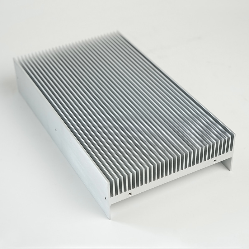
Fin shape, spacing, and height directly dictate how effectively a housing transfers heat to the surrounding air. In natural convection, wider fin gaps above 8 mm allow buoyancy-driven flow to develop, while in forced convection, fin densities of 8 to 12 fins per inch are common. Doubling the number of fins can reduce thermal resistance by as much as 40 percent, but only if the fan can overcome the resulting pressure drop. Pin fin arrays, often used on die-cast housings, increase surface area by up to 30 percent compared to straight fins in the same footprint, making them excellent for omni-directional airflow. The aspect ratio of a fin (height divided by gap) must stay within manufacturing limits; exceeding 20:1 is typically reserved for precision extrusion.
Manufacturing Methods Compared: Extruded, Die-Cast, and Stamped Housings
| Process | Material Options | Thermal Conductivity (W/m-K) | Per-Unit Cost at Volume | Best For |
|---|---|---|---|---|
| Extrusion | 6063, 6061 aluminum | 200 | Moderate | High aspect ratio fins, linear shapes |
| Die-Casting | A380, ADC12 aluminum | 100 | Low at high volumes | Complex 3D shapes, integrated mounts |
| Stamping | Aluminum, copper sheet | 200-385 | Lowest | Thin, lightweight, low-profile cooling |
Extrusion delivers maximum conductivity from wrought alloy but limits geometry to a constant cross-section. Die-casting empowers designers to combine mounting brackets, connector cutouts, and complex fins in one piece, although the lower conductivity of cast alloy must be offset with thicker cross-sections. Stamped housings excel in consumer electronics where thin sheet metal folds into functional, low-cost heat spreaders.
Surface Treatments: Anodizing and Beyond
Raw aluminum has a surface emissivity of only about 0.05, meaning it radiates very little heat. A black anodized finish raises emissivity to 0.80 or higher, dramatically improving passive radiation cooling. In natural convection environments, this surface change alone can drop component temperatures by 5 to 10 degrees C. Electroplating with nickel or using chemical conversion coatings provides corrosion resistance without sacrificing conductivity, essential for outdoor telecom housings. However, thick paint layers add thermal interface resistance; optimal coatings are kept below 25 microns to avoid insulating the metal underneath.
Practical Application Examples Across Industries
- High-power LED streetlights rely on die-cast aluminum housings with integrated pin fins to passively cool arrays drawing over 150 W, maintaining LED junction temperatures under 85 degrees C.
- CPU coolers for servers combine copper heat pipes with aluminum extruded housing sections, handling continuous thermal loads of 200 W in a 2U rack space.
- Automotive engine control units use sealed, anodized die-cast housings that dissipate 15-25 W while protecting electronics from water, salt, and under-hood temperatures exceeding 105 degrees C.
- Power inverters for solar farms employ large extruded housing profiles with deep vertical fins, achieving natural convection thermal resistances below 0.15 degrees C/W across multi-kilowatt modules.
Selection Criteria: Matching Housing to Heat Load
The first step is calculating the maximum allowable thermal resistance. Using the formula Rth = (Tjunction_max - Tambient) / Power, a processor dissipating 50 W with a 125 degrees C junction limit in a 65 degrees C ambient requires a housing with total resistance under 1.2 degrees C/W. This value must encompass the thermal interface material, the housing conduction path, and convection from fins to air. A housing built from 6063 aluminum with 25 mm tall fins and moderate airflow of 1.5 m/s can achieve a case-to-air resistance of approximately 0.8 degrees C/W, leaving headroom for the interface. Always derate for altitude and dust accumulation, which can reduce cooling performance by up to 20 percent over the product life.
Cost and Lifetime Value Analysis
While an extruded housing may have a higher per-unit tooling cost for low volumes, die-casting becomes unbeatable when quantities exceed 5,000 pieces per year, slashing machining labor by around 30 percent. The real value emerges in field reliability: a well-designed heat sink housing prevents temperature-induced failure rates from climbing exponentially. For every 10 degrees C reduction in semiconductor junction temperature, the mean time between failures roughly doubles. Therefore, investing in a housing with 0.2 degrees C/W lower thermal resistance can extend equipment life from 5 to over 10 years, making the initial premium negligible compared to downtime and replacement cost.


