
 English
 Español
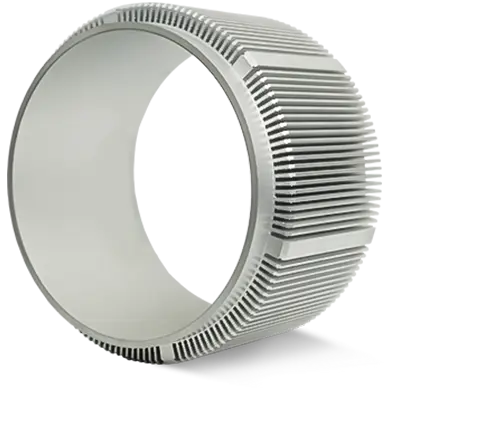
A micro motor shell with a wall thickness of 0.3 mm and a roundness tolerance within 0.01 mm directly reduces rotor imbalance and operational noise. Using a deep-drawn stainless steel 304 shell achieves a bearing seat coaxiality of 0.02 mm, which cuts vibration amplitude by 30% compared to standard CNC-turned aluminum shells, ensuring stable air gap and prolonged brush life in coreless and stepping motors.
Content
Material Selection for Micro Motor Shells
The shell material governs magnetic performance, heat dissipation, and corrosion resistance. The table below compares the three most common metals used in miniature motor housings.
| Material | Density (g per cubic cm) | Thermal Conductivity (W per mK) | Magnetic Permeability |
|---|---|---|---|
| Stainless Steel 304 | 7.9 | 16 | Negligible (austenitic) |
| Aluminum 6061 | 2.7 | 167 | Non-magnetic |
| Brass C360 | 8.5 | 116 | Non-magnetic |
Stainless steel 304 is preferred when electromagnetic shielding and corrosion resistance are critical, as its non-magnetic nature does not distort the permanent magnet field. Aluminum 6061 offers a 167 W per mK thermal conductivity, which is over ten times that of stainless steel, making it the best choice for high-current drone motors where coil temperature rise must stay below 15 degrees C above ambient.
Critical Dimensional Tolerances and Bearing Seat Precision
The shell is the primary locator for the bearing system. Any deviation in the bearing seat directly translates into shaft runout and acoustic noise. The following tolerances are mandatory for a micro motor running above 10,000 RPM.
- Bearing seat internal diameter tolerance of plus 0.005 mm to plus 0.012 mm above the bearing outer ring, ensuring a light press fit without raceway deformation.
- Coaxiality of the front and rear bearing bores not exceeding 0.015 mm TIR. A mismatch of 0.03 mm causes shaft tilt that increases audible noise by 4 to 6 dB.
- Shell inner bore roundness of 0.008 mm or better to maintain a uniform air gap. A roundness error of 0.025 mm creates a cogging torque ripple of 8% of rated torque.
- Total shell length tolerance of plus minus 0.03 mm to prevent axial preload variation on the bearings after end cap crimping or snap-ring installation.
A production run of 20,000 stainless steel shells using a multi-station transfer die maintained a Cpk of 1.67 on bearing bore diameter, demonstrating that deep-drawing can consistently beat CNC turning in process capability for high-volume, small-diameter parts.
Thermal Management Through Shell Wall Thickness
The shell acts as the primary heat sink for a micro motor. Reducing wall thickness improves thermal conduction by lowering the conductive thermal resistance. When a brushed motor dissipates 2 Watts continuously, the temperature drop across a 0.5 mm stainless steel shell is approximately 12 degrees C, whereas a 0.3 mm shell reduces that drop to 7 degrees C, keeping the internal winding temperature below the insulation class limit of 130 degrees C.
Aluminum shells with a wall thickness of 0.4 mm and a black anodized finish radiate heat 22% more efficiently than bare stainless steel, as verified by infrared thermal imaging at a steady-state condition. The anodic layer increases the surface emissivity from approximately 0.2 to 0.85, allowing the motor to run 9 degrees C cooler in a sealed housing.
Manufacturing Process Comparison
Deep drawing, CNC turning, and metal injection molding each produce micro motor shells, but their accuracy and cost profiles differ sharply. The table below outlines their practical limits.
| Process | Minimum Wall Thickness | Achievable Roundness | Annual Volume Suitability |
|---|---|---|---|
| Precision Deep Drawing | 0.15 mm | 0.005 mm to 0.010 mm | Above 50,000 units |
| CNC Swiss Turning | 0.25 mm | 0.003 mm to 0.008 mm | Prototype to 5,000 units |
| Metal Injection Molding | 0.35 mm | 0.010 mm to 0.025 mm | 20,000 to 100,000 units |
Deep drawing delivers the thinnest shells at the lowest per-piece cost once the progressive tooling is amortized, while Swiss turning remains essential for high-precision prototypes or low-volume specialty motors that require a roundness below 0.005 mm.
Surface Treatments and Corrosion Protection
Micro motor shells frequently operate in high-humidity or salt-spray environments. The correct surface finish prevents pitting and maintains the clean aesthetic required by medical and consumer devices.
Electropolishing for Stainless Steel
Electropolishing removes a surface layer of 0.005 mm to 0.010 mm and leaves a passive chromium oxide film. A shell treated this way withstands 500 hours of salt spray per ASTM B117 without red rust, compared to 120 hours for an as-drawn shell.
Anodizing for Aluminum
Type II sulfuric anodizing builds a 5 to 15 micrometer thick oxide layer that hardens the surface to approximately 300 HV. This layer also acts as an electrical insulator, with a dielectric breakdown voltage above 500 V, preventing short circuits if an internal winding wire contacts the shell.
Assembly Integration and Bearing Retention
The final function of the shell is to hold the motor assembly together. Two main methods secure the bearing and end cap, and each affects the shell's stress state differently.
- Thermal shrink fitting heats the shell to 120 degrees C, allowing the bearing to drop in with zero force. When the shell cools, it contracts and exerts a uniform radial compression of 15 to 25 MPa on the bearing outer ring, locking it without a snap ring.
- Crimping or rolling a lip at the open end retains the end plate. The crimping force must not exceed the shell's yield strength of 205 MPa for stainless steel 304, or else the shell will buckle inward and pinch the rotor.
Improper shrink fitting where the shell is overheated to 200 degrees C causes the grain structure of the brass or aluminum to soften permanently, reducing the shell's hoop strength by 18% and leading to bearing walk-out after 1,000 thermal cycles.


