
 English
 Español
Content
- 1 What Is an Aluminum Extrusion Motor Casing?
- 2 Why Aluminum Is Used for Motor Housings
- 3 Benefits of Aluminum Motor Housings
- 4 Aluminum Extrusion Process for Motor Housings
- 5 Extruded Motor Housing vs Cast Motor Housing
- 6 Aluminum vs Steel Motor Housing
- 7 Best Aluminum Alloy for Motor Housing
- 8 Heat Dissipation in Electric Motors and Cooling Fin Design
- 9 Water Cooled Motor Housing
- 10 Design Considerations for Aluminum Motor Housing Extrusions
- 11 Motor Housings for Electric Vehicles
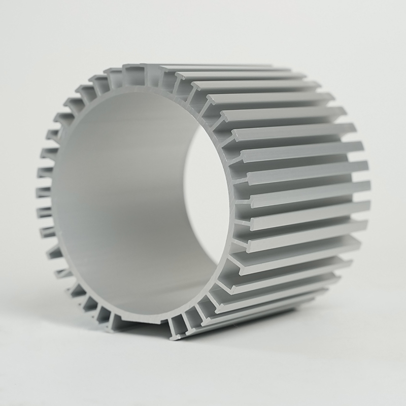
What Is an Aluminum Extrusion Motor Casing?
An aluminum extrusion motor casing is an electric motor housing produced by forcing a heated aluminum billet through a precision-shaped die, generating a continuous profile that forms the structural shell of the motor. Unlike castings — which are poured into molds and solidify in a cavity — extruded casings are shaped under compressive force, producing a dense, consistent grain structure along the entire length of the profile.
The extrusion process defines the cross-sectional geometry of the casing in a single pass: the bore diameter, wall thickness, mounting flange geometry, and cooling fin profiles are all formed simultaneously as the material passes through the die. The resulting tube is then cut to length, machined at the bore and end faces, and fitted with end shields to complete the motor assembly. This approach is particularly well suited to fractional and integral horsepower motors in the 0.1 kW to 75 kW range, where volume production demands dimensional consistency and tight tolerances on the stator bore.
Extruded motor casings are the dominant format in servo motors, BLDC motors, stepper motors, and a growing share of EV traction motor frames — any application where weight, thermal management, and repeatable geometry across production runs are non-negotiable.
Why Aluminum Is Used for Motor Housings
Aluminum's adoption as the default motor housing material for modern electric motors is driven by a combination of physical properties that directly address the engineering challenges of motor design: heat, weight, and manufacturability.
Thermal conductivity is the most critical property. Aluminum conducts heat at approximately 160–205 W/m·K depending on alloy, compared to cast iron at 40–50 W/m·K and steel at 15–50 W/m·K. In a motor housing, higher thermal conductivity means heat generated by copper losses in the windings and iron losses in the stator laminations transfers more rapidly to the outer surface, where it can be dissipated to ambient air or a liquid coolant circuit. This directly limits the peak winding temperature — the primary determinant of motor service life and continuous power rating.
Density is the second decisive factor. Aluminum at 2.7 g/cm³ is roughly one-third the density of steel (7.8 g/cm³) and cast iron (7.2 g/cm³). For the same housing geometry, an aluminum casing is approximately 65% lighter than its ferrous equivalent. In mobile applications — robotics, electric vehicles, aerospace — this weight reduction has compounding effects on system efficiency and dynamic performance.
Additional properties reinforcing aluminum's suitability include natural corrosion resistance through surface oxide formation, non-magnetic behavior (critical for minimizing eddy current interference with motor magnetic circuits), and compatibility with anodizing, powder coating, and other surface treatments that extend service life in harsh environments.
Benefits of Aluminum Motor Housings
The case for aluminum motor housings extends beyond raw material properties into manufacturing economics and system-level performance advantages:
- Higher continuous power density: Efficient heat extraction through the housing wall allows designers to operate stator windings at higher current densities without exceeding thermal limits, increasing the continuous torque output for a given frame size.
- Weight reduction at system level: Lighter housings reduce the unsprung or moving mass in the application, improving dynamic response in servo and robotics contexts and extending range in EV applications.
- Dimensional stability: Extruded aluminum profiles maintain tight bore tolerances across production batches, reducing the machining allowance required and shortening cycle times in high-volume motor assembly.
- Integrated cooling geometry: Fins, channels, and jacket features can be built directly into the extrusion profile at no additional material cost, eliminating the need for secondary cooling attachments.
- Machinability: Aluminum alloys machine approximately 3–5 times faster than steel under equivalent cutting conditions, reducing tooling wear and per-part machining cost at the bore, flange, and end-face operations.
- Recyclability: Aluminum retains approximately 95% of its embodied energy when recycled, a material property increasingly valued in motor manufacturing supply chains targeting lifecycle carbon reduction commitments.
Aluminum Extrusion Process for Motor Housings
Producing a motor housing by extrusion follows a defined sequence that converts a cast billet into a net-shape structural profile ready for secondary machining:
- Billet preparation: A cylindrical aluminum billet — typically 6xxx or 2xxx series alloy — is heated to 450–500°C, reaching the plastic deformation range without melting.
- Die pressing: A hydraulic press ram forces the softened billet through a precision steel die. The die opening defines the exact cross-sectional profile of the casing, including bore diameter, wall geometry, fin array, and any integral keyways or mounting features.
- Profile emergence and stretching: The extruded profile exits the die and is drawn along a run-out table. After cooling, it is stretched under tension to relieve residual stress and correct any minor bow introduced during extrusion.
- Age hardening (T5 or T6): For 6061 and 6063 alloys, artificial aging in an oven at 160–180°C for several hours precipitates Mg₂Si hardening phases, achieving target mechanical properties.
- Sawing to length: The profile is cut to motor frame length with allowance for face machining.
- CNC machining: The bore is finish-machined to the required concentricity and surface finish for stator press-fit. End faces are faced flat and perpendicular. Mounting holes, drain ports, and connector entries are drilled and tapped.
The entire sequence from billet to finished housing can be completed in hours for standard profiles, giving extrusion a lead-time advantage over casting processes that require pattern tooling, sand preparation, and longer heat treatment cycles.
Extruded Motor Housing vs Cast Motor Housing
The choice between extrusion and casting determines the motor housing's geometry freedom, production economics, and structural properties. Neither process is universally superior — the decision depends on production volume, geometric complexity, and application requirements.
| Criterion | Extruded Housing | Die-Cast Housing |
|---|---|---|
| Geometry freedom | Prismatic / constant cross-section only | Full 3D geometry, including flanges and complex ends |
| Tooling cost | Low (simple steel die, $500–$5,000) | High (hardened steel die, $20,000–$150,000+) |
| Material density / porosity | Dense, low porosity (compressive forming) | Higher porosity risk; dependent on gating quality |
| Tensile strength (6061-T6 / A380) | ~310 MPa | ~320 MPa (A380 die cast) |
| Thermal conductivity | 160–180 W/m·K (6061) | 96 W/m·K (A380 die cast) |
| Minimum order / break-even volume | Very low (even single-piece viable) | High volume required to amortize tooling |
| Lead time | Days to weeks | Weeks to months (tooling dependent) |
A practical rule: extrusion is the default for cylindrical motor frames in low-to-medium volume production, particularly where thermal performance and bore concentricity are critical. Die casting becomes economically attractive above approximately 10,000–50,000 units per year and where the housing geometry requires integral features — connector housings, multi-axis mounting bosses, or complex end-bell geometries — that cannot be produced in a constant cross-section profile.
Aluminum vs Steel Motor Housing
Steel motor housings — typically fabricated from rolled and welded mild steel or machined from solid bar — remain in use for large industrial motors, harsh-environment applications, and legacy designs where frame standards were established around ferrous materials. The comparison against aluminum is not straightforward: both materials have distinct performance domains.
Steel offers higher tensile strength (mild steel ~400 MPa vs 6061-T6 at ~310 MPa) and better impact toughness, which matters in heavy-duty industrial motors subject to shaft-transmitted shock loads or external mechanical impacts. Steel housings are also more readily weldable, allowing field repair in some applications. However, steel's thermal conductivity disadvantage (approximately 10× lower than aluminum for equivalent alloy grades) means that steel-housed motors accumulate heat significantly faster under equivalent load conditions, requiring larger frame sizes or additional cooling apparatus to achieve the same continuous power rating.
For the majority of modern motor applications — servo drives, BLDC motors, EV traction units, industrial automation — the thermal and weight advantages of aluminum outweigh steel's strength advantage, particularly as operating speeds increase and motor designers push power density upward. The breakpoint is roughly at motors above IEC frame size 355, where wall thickness requirements for structural integrity begin to narrow aluminum's weight advantage and cast iron or fabricated steel becomes competitive again.
Best Aluminum Alloy for Motor Housing
Alloy selection for motor housings requires balancing extrudability, thermal performance, mechanical strength, and corrosion resistance. Three alloys account for the majority of extruded motor housing production:
- 6061-T6: The workhorse alloy for motor housings requiring structural integrity. Tensile strength ~310 MPa, thermal conductivity ~167 W/m·K. Responds well to T6 aging treatment. Good machinability and weldability. Best suited for housings with integral mounting flanges and applications requiring anodizing for corrosion protection. Slightly harder to extrude into complex fin geometries than 6063.
- 6063-T5/T6: The preferred alloy for thermally optimized housings with dense fin arrays. Thermal conductivity ~200 W/m·K — approximately 20% higher than 6061. Lower strength (~240 MPa T6) but excellent extrudability allows thinner fin walls and finer pitch arrays. The standard choice for heat-sink-style motor housings where passive cooling geometry is the primary design driver.
- 6082-T6: Common in European motor manufacturing. Strength comparable to 6061 (~310 MPa) with good corrosion resistance. Often specified in place of 6061 for industrial motor applications meeting EN/IEC standards.
For water-cooled motor housings, where the jacket is machined directly into the extrusion wall, 6061-T6 is generally preferred because the higher strength tolerates the hoop stress from coolant pressure more reliably than 6063. For air-cooled motors where maximizing passive fin performance is the goal, 6063-T5 is typically optimal — the conductivity gain from 6063 over 6061 can reduce peak winding temperature by 5–10°C under equivalent load and ambient conditions.
Heat Dissipation in Electric Motors and Cooling Fin Design
Thermal management is the central engineering challenge in motor housing design. Heat is generated at two primary sources: copper losses (I²R heating) in the stator windings, which dominate at rated load, and iron losses (eddy current and hysteresis) in the stator laminations, which scale with switching frequency. Both must be conducted through the stator stack, across the stator-to-housing interface, through the housing wall, and ultimately rejected to the environment.
The stator-to-housing thermal interface resistance is a critical and often underestimated variable. A press-fit or shrink-fit stator in an aluminum bore achieves an interface conductance of approximately 1,000–5,000 W/m²·K depending on fit pressure and surface finish. Loose or clearance fits — sometimes seen in modular motors designed for easy stator replacement — can reduce this figure by an order of magnitude, negating much of the aluminum housing's conductivity advantage.
Cooling Fin Design Principles
External cooling fins increase the surface area available for convective heat rejection. Key design parameters:
- Fin pitch: Closer fin spacing increases total surface area but raises flow resistance, reducing natural convection effectiveness. For natural convection cooling, fin pitch of 5–10 mm is typical; for forced-air cooling with an internal fan, pitches of 3–5 mm are viable.
- Fin height: Taller fins increase surface area but diminish marginal return due to fin efficiency losses — heat conduction diminishes along the fin length. Practical fin heights for extruded motor housings range from 8–25 mm.
- Fin orientation: Longitudinal fins (parallel to the motor axis) are standard for extruded housings because they are formed naturally in the extrusion direction. Circumferential fins require separate machining operations or a casting process.
- Base wall thickness: The wall between the stator bore and the fin base must be thick enough to conduct heat radially without creating a bottleneck. Minimum base wall thickness of 4–6 mm is typical for housings up to 100mm frame.
Water Cooled Motor Housing
Liquid cooling dramatically increases the heat rejection capacity of a motor housing, enabling continuous power densities 2–4× higher than air-cooled equivalents of the same frame size. In a water-cooled aluminum motor housing, a helical or axial coolant channel is machined into the outer wall of the bore — or formed as an integral feature in the extrusion cross-section — through which chilled water or a water-glycol mixture is circulated.
Two jacket configurations are common in extruded aluminum housings:
- Machined spiral groove: A helical channel is CNC-machined into the outer surface of the bore wall, then sealed by pressing or shrinking an outer sleeve over the channel. This approach allows precise channel geometry and is used in high-performance servo and EV motor applications.
- Integral extrusion jacket: The coolant channel is formed as a closed cavity within the extrusion die, producing a hollow wall section that acts as the coolant passage. This eliminates the secondary machining operation but requires a more complex die and restricts channel geometry to the extrusion direction.
Water-cooled housings are standard in EV traction motors, high-cycle industrial servo drives, and spindle motors where sustained peak performance is required. The coolant flow rate, inlet temperature, and channel geometry are sized during thermal simulation to maintain peak winding temperature below the insulation class rating — typically 155°C (Class F) or 180°C (Class H) — under the worst-case duty cycle.
Design Considerations for Aluminum Motor Housing Extrusions
Designing an aluminum extrusion for motor housing application requires coordinating thermal, structural, and manufacturing constraints simultaneously. The following considerations govern most housing development programs:
- Bore concentricity and cylindricity: The finished bore must maintain concentricity to the motor shaft axis within the tolerance specified by the bearing arrangement. Typical requirements are 0.02–0.05 mm TIR on the bore relative to the end shield spigot fits. This drives minimum wall thickness to avoid distortion during stator press-fitting.
- Wall thickness uniformity: Uneven wall thickness in an extruded profile introduces asymmetric thermal gradients and residual stresses after aging. Die design must balance metal flow to achieve uniform wall thickness around the bore circumference, particularly at fin root transitions.
- Fin geometry and extrudability: Sharp fin tips and high aspect-ratio fins (height-to-width ratio above 10:1) push the limits of extrusion die life and require higher press pressures. Minimum fin tip radius of 0.5 mm and maximum aspect ratio of 8:1–10:1 are practical guidelines for production tooling.
- Thermal expansion management: Aluminum's coefficient of thermal expansion (~23 µm/m·°C) is approximately twice that of steel stator laminations (~12 µm/m·°C). The press-fit stator retention force decreases as the housing heats up. Housing bore diameter and interference fit must be sized to maintain adequate retention at maximum operating temperature.
- Machining allowances: Extrusion tolerances on bore diameter are typically ±0.3–0.5 mm, requiring finish machining. Allowances of 0.5–1.0 mm per side are included in the extrusion bore diameter to guarantee material for clean-up during CNC turning.
- Surface treatment: Hard anodizing (20–50 µm, Type III) significantly improves bore wear resistance where stator lamination edges contact the housing, and provides corrosion protection in outdoor or high-humidity environments. Clear anodize or alodine treatments are used where electrical conductivity of the outer surface must be maintained for EMC bonding.
Motor Housings for Electric Vehicles
Electric vehicle traction motors represent the most demanding application segment for aluminum motor housings, combining high continuous power density, aggressive duty cycles, vibration loading, and strict weight targets within a thermally challenging underhood or in-wheel environment. Virtually all modern EV traction motors use aluminum housings, with die casting currently the dominant process at high production volumes and extrusion playing a secondary role in lower-volume performance and commercial vehicle applications.
EV motor housings face specific design requirements not present in industrial motor applications:
- Integrated liquid cooling is mandatory: Peak power events in EV traction applications — launch, passing, hill climbing — generate heat at rates that cannot be managed by air cooling alone. All production EV traction motor housings incorporate water-glycol jacket cooling, typically with coolant supplied from the same loop as the inverter and battery thermal management system.
- Structural integration: EV motor housings frequently serve as structural members of the powertrain subframe or cradle, carrying drivetrain torque reaction loads in addition to their thermal and retention functions. This requires higher material strength than a comparable industrial motor housing, driving alloy selection toward 6061 or higher-strength 7xxx series in some cases.
- NVH performance: Electric drivetrains have no masking combustion noise, making electromagnetic torque ripple and bearing noise more perceptible. Housing stiffness and modal frequency are design parameters that directly affect cabin NVH, requiring FEA-optimized rib and wall geometry.
- Ingress protection: EV motor housings typically require IP67 or IP69K ratings, demanding precision sealing surfaces at the end shields and connector entries — tolerances that must be held through the full thermal cycle of the operating environment.
For lower-volume EV programs — specialty vehicles, commercial EVs, motorsport, and performance variants — extruded and machined aluminum housings remain viable and competitive, particularly where the flexibility to iterate on cooling channel geometry between development builds outweighs the per-unit cost advantage of a committed die-casting tool.


