
 English
 Español
Content
What Is a Heat Sink Housing?
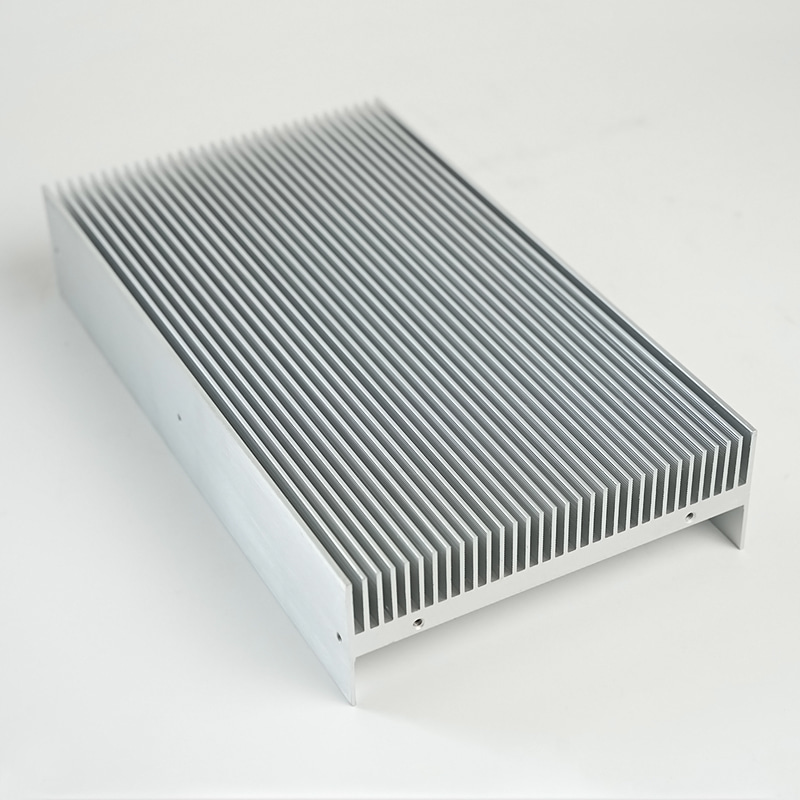
A heat sink housing is a structural enclosure that integrates thermal management directly into the component housing itself. Rather than attaching a separate heat sink to an existing chassis, the housing is designed and fabricated with fins, channels, or mass specifically to conduct and dissipate heat away from internal components. This approach is widely used in LED lighting modules, power electronics, motor drives, and industrial control equipment where space, weight, and thermal performance must all be optimized simultaneously.
The defining characteristic is the dual function: the same part that protects and mounts internal electronics also acts as the primary thermal path. Heat generated by semiconductors, capacitors, or other heat-producing elements is transferred by conduction through the housing wall and then dissipated by convection into the surrounding air—or into a coolant in liquid-cooled variants. This eliminates the thermal interface resistance introduced by bolted-on heat sink assemblies and reduces overall part count.
Materials and Their Thermal Properties
Material selection is the single most consequential decision in heat sink housing design. The most common options are aluminum alloys, copper alloys, and thermally conductive polymers, each offering a distinct balance of conductivity, weight, cost, and manufacturability.
Aluminum Alloys
Aluminum is the dominant choice across most industries. Alloys such as 6061 and 6063 offer thermal conductivity in the range of 150–200 W/m·K, combined with low density (2.7 g/cm³), excellent corrosion resistance, and compatibility with extrusion, die casting, and CNC machining. Extruded aluminum heat sink housings are particularly cost-effective in high volumes and allow complex fin profiles to be produced in a single pass without secondary operations.
Copper Alloys
Copper delivers thermal conductivity of approximately 385–400 W/m·K—roughly twice that of aluminum—making it the preferred material when extreme heat flux density must be managed in a compact volume. The tradeoff is density (8.9 g/cm³) and cost. Copper heat sink housings are typically found in RF power amplifiers, high-current power supplies, and precision laser systems where thermal resistance budgets are extremely tight.
Thermally Conductive Polymers
Injection-moldable thermally conductive polymers typically achieve conductivity of 1–20 W/m·K—far below metals—but offer significant advantages in electrical insulation, design freedom, and weight. They are used in consumer electronics, EV battery housings, and LED downlights where the lower thermal loads do not demand metallic conductivity and where complex three-dimensional geometries would be expensive to machine.
| Material | Thermal Conductivity (W/m·K) | Density (g/cm³) | Typical Application |
|---|---|---|---|
| Aluminum 6063 | 200 | 2.7 | LED drivers, motor drives, industrial enclosures |
| Copper C110 | 391 | 8.9 | RF amplifiers, high-current power supplies |
| Thermally Conductive Polymer | 5–20 | 1.4–1.6 | Consumer electronics, EV battery modules |
Manufacturing Processes
The manufacturing route determines the achievable fin geometry, dimensional tolerance, surface finish, and unit economics. Three processes account for the vast majority of heat sink housing production.
Extrusion
Aluminum extrusion is the highest-volume process for heat sink housings used in lighting and power electronics. A heated aluminum billet is forced through a shaped die, producing a continuous profile that is then cut to length and, if required, further machined. Extruded fins can be as thin as 1.2 mm with aspect ratios exceeding 10:1, maximizing surface area without significant weight penalty. Tooling costs are low relative to die casting, and lead times are short once a die is qualified.
Die Casting
High-pressure die casting allows three-dimensional geometries that extrusion cannot produce—integrated bosses, mounting flanges, connector pockets, and internal flow channels can all be formed in a single shot. Aluminum die casting alloys such as ADC12 have slightly lower thermal conductivity (~96 W/m·K) than wrought alloys due to higher silicon content, a tradeoff that must be accounted for in thermal modeling. Die casting is preferred when the housing serves a complex mechanical role in addition to its thermal function.
CNC Machining
Machining from billet aluminum or copper is used for prototypes, low-volume specialty products, and applications requiring tight tolerances (±0.01 mm or better) that casting and extrusion cannot reliably achieve. Skived fin machining—where fins are literally shaved from a solid block—can produce fin pitches below 0.5 mm and surface areas per unit volume that exceed what any other process can deliver, making it the preferred approach for high-performance computing and aerospace thermal management.
Fin Design and Airflow Considerations
The fin array geometry governs how effectively the housing transfers heat to the surrounding air. Key parameters include fin height, thickness, pitch (center-to-center spacing), and the orientation of the fins relative to natural or forced airflow.
For natural convection applications—the majority of LED luminaires and outdoor power enclosures—vertical fins aligned with the chimney effect airflow path outperform horizontal fins by 20–40% at identical fin dimensions. Fin spacing must balance two competing effects: closer spacing increases total surface area but reduces the cross-sectional flow area, increasing air resistance and potentially causing the boundary layers from adjacent fins to merge, degrading convective efficiency.
In forced convection designs where a fan or blower is present, fin pitch can be tighter because pressure-driven airflow overcomes the resistance that limits natural convection. Pin fin arrays—cylindrical or square pins rather than planar fins—are sometimes used when airflow direction is uncertain or multi-directional, since they present similar resistance regardless of approach angle.
Surface treatments also play a role. Anodizing aluminum to a thickness of 10–25 µm increases emissivity from approximately 0.05 (bare aluminum) to 0.8–0.9, meaningfully improving radiative heat dissipation in high-temperature environments and extending the effective operating range of the housing at zero additional weight or volume.
Key Applications Across Industries
Heat sink housings appear across a remarkably broad range of products wherever power density and thermal reliability intersect.
- LED Lighting: High-bay fixtures, streetlights, grow lights, and architectural luminaires all rely on extruded or die-cast aluminum heat sink housings to maintain LED junction temperatures below 85°C, the threshold above which lumen output and lifespan degrade sharply.
- Power Electronics: Variable frequency drives, on-board chargers for EVs, and solar inverters mount IGBTs and MOSFETs directly to the inner wall of the housing, using the entire chassis as a spreader and radiator.
- Telecommunications: Outdoor small cell base stations and fiber optic amplifiers use sealed, passively cooled housings where fins provide thermal management without any moving parts, eliminating a key failure mode in equipment expected to run continuously for 10+ years.
- Industrial Automation: Servo drives and motion controllers in factory environments benefit from rugged aluminum housings that simultaneously provide EMI shielding, IP-rated ingress protection, and sufficient thermal capacity to handle cyclic high-load events without exceeding component temperature ratings.
- Medical Devices: Imaging equipment and surgical tools use thermally managed housings to prevent patient contact surfaces from reaching uncomfortable or unsafe temperatures during extended procedures.
Selecting the Right Heat Sink Housing for Your Application
Effective selection starts with a clear thermal budget: the maximum allowable junction temperature of the most heat-sensitive component, minus the expected ambient temperature, defines the total allowable thermal resistance from junction to ambient. That resistance is then allocated across the thermal interface material, the housing wall, and the fin-to-air convection boundary.
Beyond thermal performance, the selection must account for:
- IP rating requirements — sealed enclosures (IP65 and above) restrict airflow, favoring higher-conductivity alloys and larger external fin areas to compensate.
- Mounting orientation — natural convection efficiency drops significantly when fins are horizontal; design or orientation constraints should be flagged early in the selection process.
- Volume and cost targets — extrusion offers the best cost-performance ratio at mid-to-high volumes; die casting adds geometric flexibility at moderate cost; machining is justified only for low volumes or extreme thermal requirements.
- Regulatory compliance — RoHS, REACH, and UL requirements may influence alloy choice and surface treatment selection, particularly in consumer and medical applications.
Thermal simulation using CFD (computational fluid dynamics) tools is strongly recommended before finalizing housing geometry, particularly for natural convection designs where small changes in fin pitch or orientation can produce 15–30% differences in effective thermal resistance. Prototyping and bench testing against the actual power profile of the target electronics remain essential to validate simulation results before committing to production tooling.


