
 English
 Español
Content
Heat Sink Housing: When the Enclosure Becomes Part of the Thermal Management System
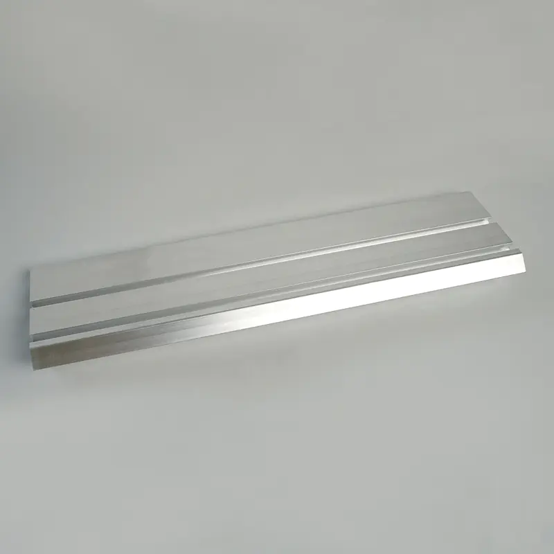
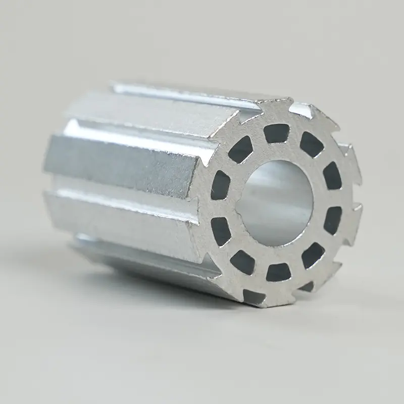
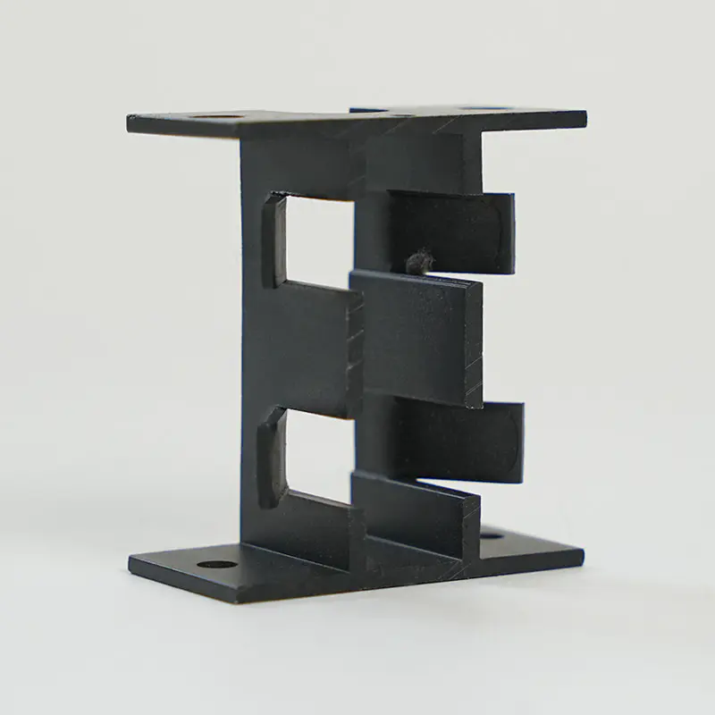
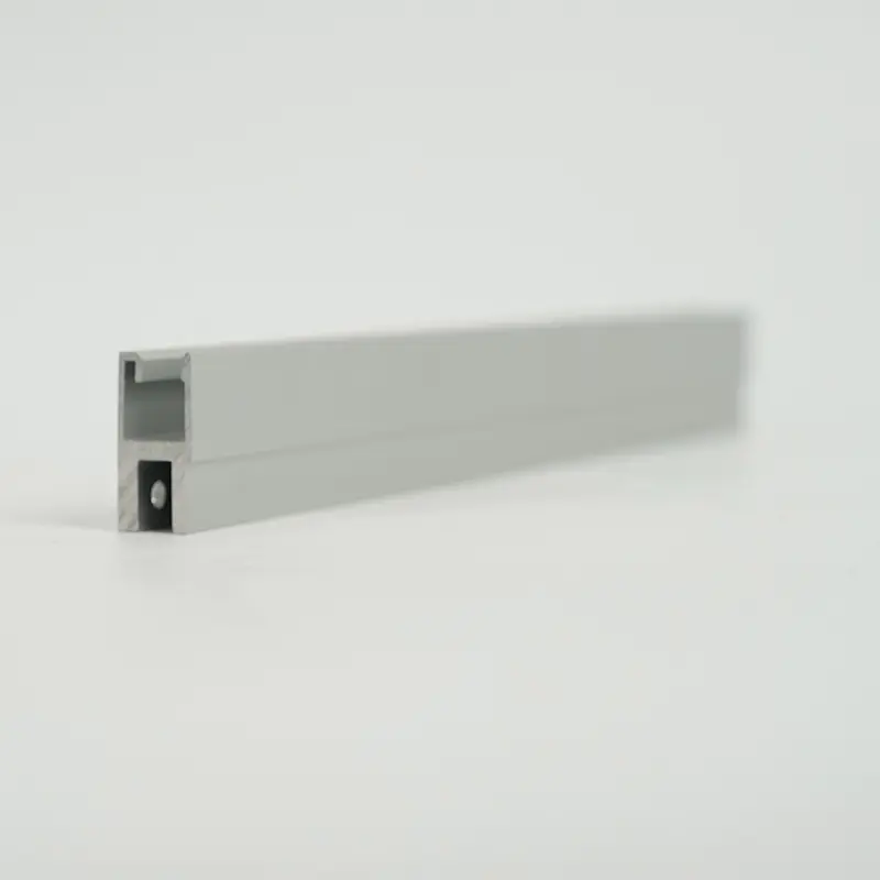
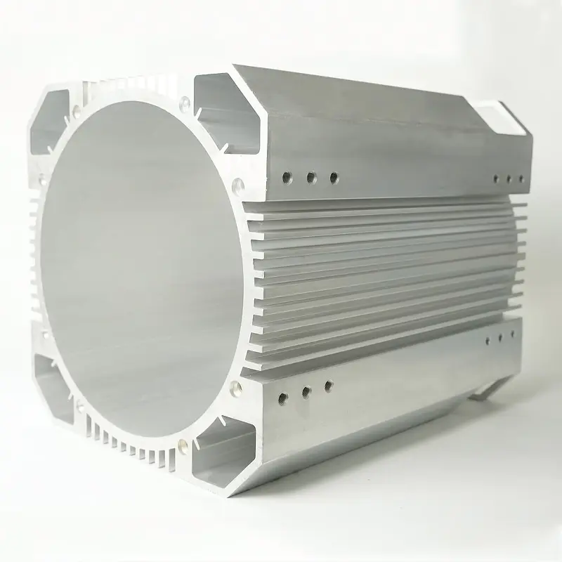
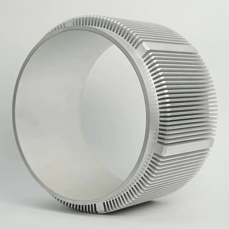
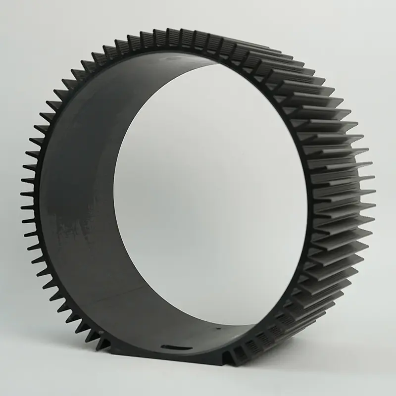
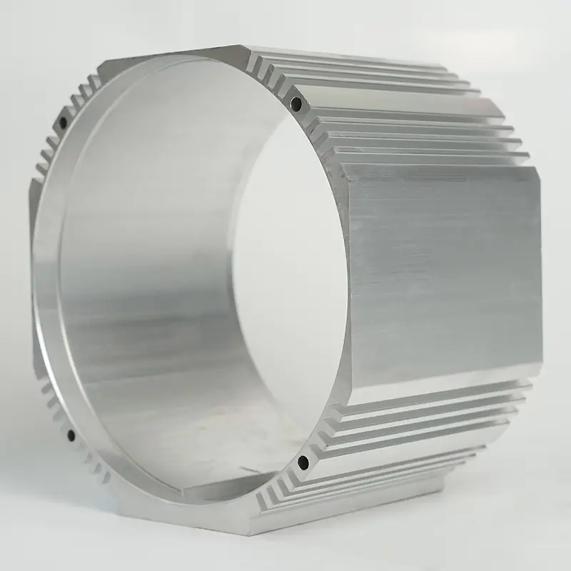
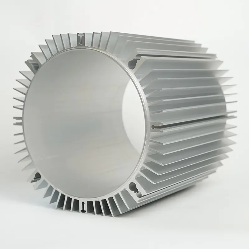
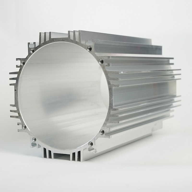
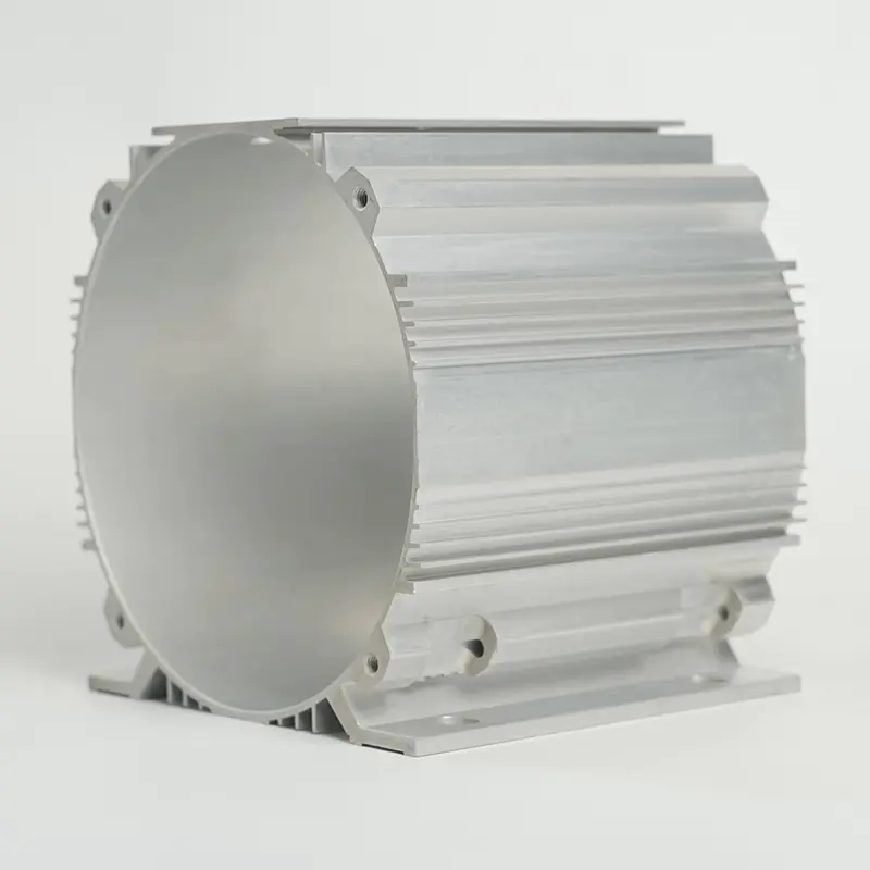
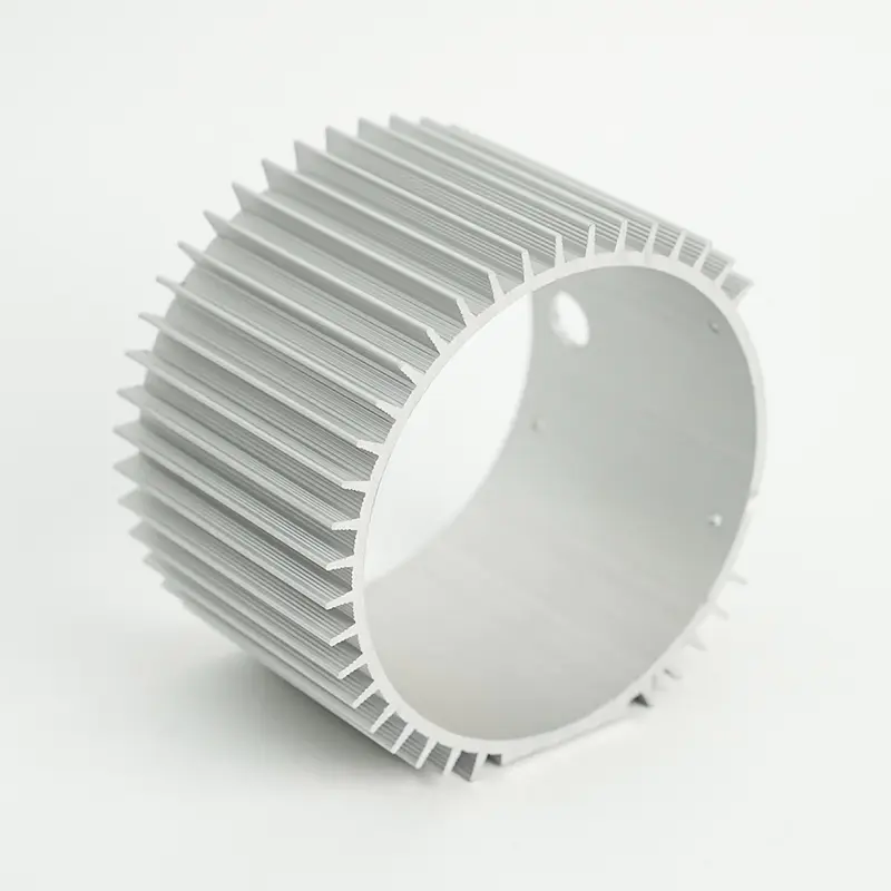
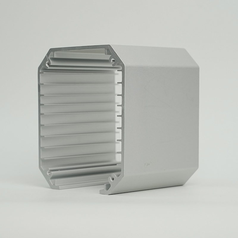
A heat sink housing combines two functions that are typically handled by separate components: it serves simultaneously as the structural enclosure of an electronic assembly and as the primary heat dissipation pathway for the components inside it. Rather than mounting a discrete heat sink to a component and then placing that assembly inside a separate chassis, a heat sink housing integrates fins, channels, or other dissipative geometry directly into the enclosure walls or base, turning the housing itself into the thermal management solution.
This approach is particularly common in LED drivers, power converters, motor controllers, industrial lighting fixtures, and outdoor-rated electronic enclosures where board-level space is constrained, where the enclosure must be sealed against ingress, and where a separate internal heat sink would create airflow dead zones or require a fan that the application cannot accommodate. The thermal and mechanical design of a heat sink housing are inseparable — optimizing one while ignoring the other reliably produces a product that fails to meet either requirement.
Materials Used in Heat Sink Housing Design
Material selection for a heat sink housing is the single most consequential design decision because it simultaneously sets the ceiling on thermal conductivity, determines the available manufacturing processes, and establishes the baseline weight and cost structure of the finished part.
Aluminum Alloys
Aluminum is the dominant material for heat sink housing applications across virtually all market segments. The thermal conductivity of common aluminum alloys falls between 130 and 210 W/m·K depending on alloy and temper — significantly lower than pure aluminum (237 W/m·K) but far superior to steel, zinc, or engineering plastics. The two most frequently specified alloys are:
- 6063-T5 — the standard extrusion alloy for heat sink profiles, with a thermal conductivity of approximately 200 W/m·K and excellent surface finish capability. Its lower silicon content compared to 6061 makes it more suitable for complex extrusion cross-sections with thin fins. The vast majority of extruded heat sink housings for LED and power electronics use 6063 or equivalent alloys (e.g., EN AW-6063 in Europe).
- ADC12 / A380 — high-silicon die casting alloys with thermal conductivity of approximately 90–100 W/m·K. The lower conductivity compared to 6063 is the trade-off for the complex three-dimensional geometry that die casting enables — integrated mounting bosses, cable entry features, and undercut fins that extrusion cannot produce. Die cast aluminum heat sink housings are standard in automotive electronics, industrial motor controls, and high-IP-rated enclosures.
Copper
Copper offers thermal conductivity of approximately 385–400 W/m·K — roughly double that of aluminum — but at three times the density and significantly higher material cost. Full copper heat sink housings are rare due to weight and cost, but copper inserts, vapor chambers, or heat pipes embedded within an aluminum housing are a well-established hybrid approach for applications where the thermal load of a specific component exceeds what an all-aluminum design can handle without exceeding junction temperature limits.
Thermally Conductive Polymers
Thermally conductive polymer compounds — typically nylon, PPS, or LCP filled with boron nitride, aluminum nitride, or carbon fiber — achieve thermal conductivities in the range of 1–20 W/m·K, which is orders of magnitude below aluminum but significantly above standard engineering plastics (0.1–0.3 W/m·K). Their competitive advantage is in applications requiring electrical isolation of the housing surface, weight reduction beyond what aluminum can achieve, and the design freedom of injection molding. LED downlights and consumer electronics power supplies represent the most common application areas for thermally conductive polymer housings.
Manufacturing Methods and Their Thermal Implications
The manufacturing process used to produce a heat sink housing determines not just the cost and geometry options but also the achievable fin density, minimum wall thickness, and — critically — the anisotropy of thermal conductivity through the part.
Extrusion
Aluminum extrusion is the most thermally efficient manufacturing route for heat sink housings because it uses 6063-series alloys with high conductivity and produces a continuous cross-section with dense, uniform fins. Extruded profiles are cut to length and machined for mounting features and cable entry points. The constraint is that the cross-section must be uniform along the extrusion axis — features that require variation in the Z-direction must be added by secondary machining. For housings that are essentially prismatic — a rectangular or cylindrical enclosure with fins on the exterior — extrusion is almost always the optimal process on both thermal and cost grounds.
Die Casting
Pressure die casting with ADC12 or A380 alloy produces three-dimensional housing geometries not achievable by extrusion, with high dimensional repeatability and minimal secondary machining for series production. The thermal conductivity penalty of the high-silicon casting alloy (~96 W/m·K vs. ~200 W/m·K for 6063) must be compensated by increased fin surface area or by accepting a higher operating temperature at steady state. For applications where the housing geometry is driven by mechanical or IP-rating requirements rather than thermal optimization, die casting is typically the appropriate process. Minimum wall thickness in die casting is approximately 1.5–2.0 mm for aluminum; fin aspect ratios are limited to approximately 5:1 without draft angle complications.
CNC Machining
Machined heat sink housings from billet 6061-T6 or 6063-T5 offer the highest geometric freedom and use the same high-conductivity alloys as extrusion. They are the standard approach for prototypes, low-volume production, and applications requiring very tight dimensional tolerances on mating surfaces. Unit cost at volume is significantly higher than extrusion or die casting, but machining allows fin geometries — including skived fins and milled pin arrays — that achieve fin densities and aspect ratios beyond what either extrusion or casting can produce. Skived fin machining, in particular, can produce fins as thin as 0.2 mm with aspect ratios above 40:1, achieving surface area densities that approach the theoretical limits for natural convection cooling.
Manufacturing Process Comparison
| Process | Typical Alloy | Thermal Conductivity | Geometry Freedom | Best Fit |
|---|---|---|---|---|
| Extrusion | 6063-T5 | ~200 W/m·K | Uniform cross-section only | LED drivers, power supplies, prismatic enclosures |
| Die Casting | ADC12 / A380 | ~96 W/m·K | High — full 3D geometry | Motor controls, automotive ECUs, IP-rated enclosures |
| CNC Machining | 6061-T6 / 6063 | ~167–200 W/m·K | Maximum — any geometry | Prototypes, low volume, high-density fin arrays |
| Injection Molding (conductive polymer) | Filled nylon / PPS | 1–20 W/m·K | High — injection moldable geometry | Consumer electronics, isolated surfaces, weight-critical |
Thermal Design Principles for Heat Sink Housings
Effective heat sink housing design requires managing the full thermal resistance chain from junction to ambient — not just maximizing fin surface area. Each stage in the chain contributes resistance, and the weakest link sets the limit on achievable junction temperature regardless of how well other stages are optimized.
The Thermal Resistance Chain
For a component mounted inside a heat sink housing, the thermal pathway runs: junction → component package → thermal interface material (TIM) → housing base → housing fins → ambient air. Total junction-to-ambient thermal resistance (θja) is the sum of all resistances in this chain. In a well-designed heat sink housing, the dominant resistance is usually the convective resistance at the fin surface — the interface between the aluminum and the air. Reducing that resistance through increased fin surface area, optimized fin spacing, or forced convection yields the largest improvement in junction temperature.
The thermal interface material between the component and the housing base is a frequently underestimated resistance source. A standard phase-change TIM pad has a thermal conductivity of approximately 3–6 W/m·K; a premium graphite sheet reaches 10–15 W/m·K; a well-applied thermal grease can achieve 8–12 W/m·K under sufficient clamping pressure. Specifying a high-conductivity housing material while using a poor TIM is a common design error that limits performance at the junction-to-case stage before the housing geometry even becomes relevant.
Natural Convection vs. Forced Convection Fin Geometry
Heat sink housing fin geometry must be matched to the airflow regime of the installation environment. Natural convection — buoyancy-driven airflow with no fan — is the default assumption for sealed or IP-rated enclosures. Under natural convection, optimal fin spacing is typically 6–12 mm for vertical fins; narrower spacing creates a chimney effect that reduces rather than increases airflow through the fin channels as boundary layers from adjacent fins merge. Fin height under natural convection is limited by the same effect — fins taller than approximately 50–75 mm begin to show diminishing returns as the air temperature rises through the channel.
For housings with forced convection (fan-cooled enclosures), fin spacing can be reduced to 2–4 mm and fin height increased substantially because the forced flow maintains velocity through the channel independent of buoyancy. Pin fin arrays — rather than plate fins — are often specified in forced convection heat sink housings because they are less sensitive to airflow direction and perform well when the inlet air angle is not perfectly aligned with the fin orientation.
Surface Finish and Emissivity
Radiation contributes meaningfully to heat dissipation from heat sink housings in natural convection environments, particularly at elevated temperatures. A bare machined aluminum surface has an emissivity of approximately 0.05–0.10 — effectively a poor radiator. Anodizing the housing surface increases emissivity to 0.80–0.90, which can reduce steady-state operating temperature by 5–15°C at typical LED driver power levels compared to a bare aluminum finish. Black anodizing provides the highest emissivity within the anodizing family; clear anodizing provides moderate improvement over bare aluminum with less visual impact. Powder coating also provides high emissivity (0.85–0.95) and additionally improves corrosion resistance for outdoor-rated housings.
IP Rating, Sealing, and Thermal Performance Trade-offs
Sealed heat sink housings — rated IP54, IP65, IP67, or higher — present a fundamental thermal design tension: the sealing requirement that protects the electronics from dust and moisture also prevents air from entering the enclosure for convective cooling of internal components. Every watt of heat generated inside a sealed housing must be conducted through the housing wall and dissipated from the exterior surface. This shifts the thermal design problem from managing internal airflow to minimizing the conductive resistance of the housing wall and maximizing the exterior convective and radiative surface.
For sealed heat sink housings, direct thermal bonding of components to the housing base — rather than mounting components to a PCB that then sits on standoffs inside the housing — dramatically reduces the number of thermal interfaces in the conduction path. LED modules, MOSFETs, and other high-dissipation components are often mounted directly to a machined pad on the interior of the housing base using TIM and clamping screws, establishing a short conduction path from junction through package through TIM to the housing wall, and then to the exterior fins.
Gasket material selection affects both sealing reliability and thermal performance at the interface. Silicone gaskets maintain their compression set characteristics across the temperature range typical of outdoor electronics (−40°C to +85°C) and do not outgas at elevated temperatures. Compressed fiber or foam gaskets are lower cost but show greater compression relaxation over time, which can reduce IP rating integrity in installations subject to thermal cycling. For heat sink housings in outdoor environments, silicone gaskets with a Shore A hardness of 40–60 represent the standard specification.